THE BLACKWOLF
Assembly Guide


ON THIS PAGE
- Tools you will need
- Regulator settings
- Inserting the hammer
- Installing the cocking arm and pellet probe
- Trigger Assembly
- Valve Assembly
- Regulator
- Bottle/Cylinder Housing Assembly
- Installing the housing
- Bottle assembly
- Cylinder Assembly
- Barrel and shroud assembly
- Final Checks and Settings
- Stock and Safety catch Replacement
INTRODUCTION
Daystate air rifles are engineered to the highest standards, but like anything else, they require repairs and servicing work to be carried out both in and out of warranty.
The aim of this guide and the accompanying video is to provide instruction on how to reassemble the Daystate Blackwolf.
In addition, a separate regulator service video is available here
For a cylinder or bottle switch we have made a separate video which can be viewed here
For fitting a carbon tensioner view here
For Trigger Adjustment video here
For Volumax fitment (TAC version only) here
Compressed air is dangerous. You should only use this guide if you are a qualified and experienced gunsmith used to working with compressed air. Before you carry out any work on the Daystate Wolverine, or any PCP air rifle for that matter, you must ensure it is not cocked, not loaded and empty of air.
TOOLS YOU WILL NEED
- Allen keys: 2mm; 2.5mm; 3mm; 4mm; 5mm
- T10 TORX bit (rifles up to July 2025)
- 10mm Deep socket
- Daystate Regulator removal tool
- Daystate Valve removal tool
- 16mm thin open-end spanner
- 22mm open-end spanner
- Tweezers
- 3-pin M5 A/T removal tool (large)- available from Daystate part number DANTITOOLXX
- Digital callipers
- O-rings used in Blackwolf
- O-ring pick
| PART NUMB. | QTY | SIZE | IMP or METRIC | SHURE | LOCATION |
|---|---|---|---|---|---|
| 4 | 2 | 14.5x1.5 | M | 70 | Breech/barrel |
| 5 | 1 | 118 | IMP | 70 | Housing b |
| 6 | 3 | 014 | IMP | 70 | valve housing |
| 11 | 1 | 007 | IMP | Urethane | valve |
| 80 | 1 | 28x1.78 | M | 70 | Barrel .22 |
| 80 | 1 | 1x1.6 | M | 70 | Barrel .177 |
| 80 | 1 | 5x1.5 | M | 70 | Barrel .30 |
| 80 | 1 | 1x1.6 | M | 70 | Barrel .25 |
| 85 | 1 | 019 | IMP | 70 | Shroud |
| 91 | 2 | 3.5x2.62 | M | 70 | gauge |
| 91 | 2 | 3.5x2.62 | M | 70 | gauge |
| 91 | 2 | 3.6x2.5 | M | 70 | gauge |
| 91 | 2 | 5x2 | M | 70 | gauge |
| 96 | 1 | 006 | IMP | Urethane | filler |
| 103 | 1 | 617 | IMP | 70 | bottle |
| 107 | 4 | 122 | IMP | 70 |
BLACKWOLF REGULATOR SETTINGS
| Calibre | Power | Pressure |
|---|---|---|
| 177 | 12 | 105 |
| 22 | 12 | 105 |
| 177 | 20 | 110 |
| 177 | 31 | 190 |
| 22 | 45 | 160 |
| 22 | 61 | 190 |
| 25 | 67 | 195 |
| 30 | 95 | 195 |
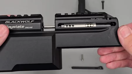
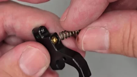
INSERTING THE HAMMER

Hammer and power adjuster assembly
02:06 Slide the hammer in place with the cut-out uppermost into the breech block and drop the cocking-dog though the slot in the scope rales and slide it backwards into position. Tighten the two 2mm screws.
02:50 Insert hammer spring.
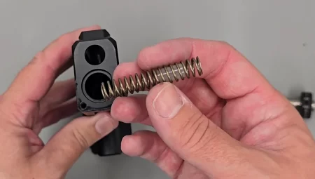
insert the hammer spring, different rades are avalable and are color coded
03:15 replace hammer spring adjuster and fasten in position the end cap using a 3mm allen key and if a UK sub 12 ft/lbs version the three pin anti tamper screw.
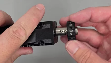
inserting the power adjuster wheel
power adjuster cap replacement
INSTALLING THE COCKING ARM AND PELLET PROBE
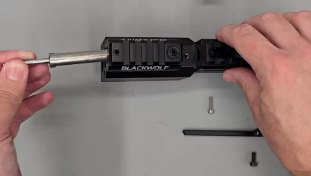
Inserting the breech bolt through the front of the block
04:35 insert the pellet probe in through the front of the breech block with the cutaway side downwards until fully in position (05:27).
Correct breech bolt alignment
05:38 Insert the cocking arm into the left or right side as preferred. Do not overtighten the bolt pivot screw as this can distort the pivot bush. Align the two cocking arm pegs, then position and tighten the retaining screw with a 2.5mm allen key (06:50).
Cocking lever in position with screw in place
07:25 Replace the blanking plate and securing screw, reinstall the pellet probe detent plate with a 2mm allen key.
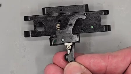
TRIGGER ASSEMBLY
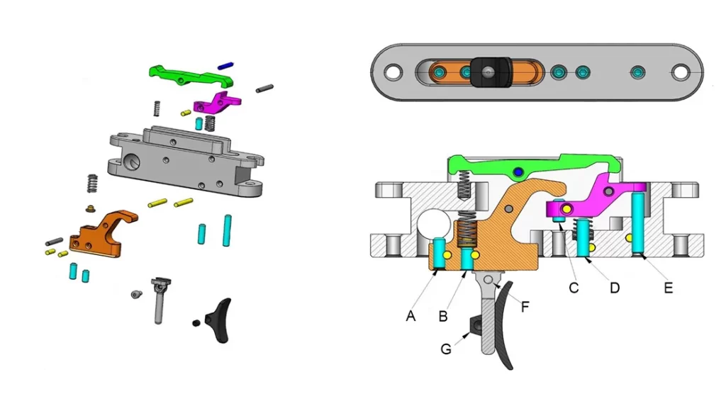
Trigger diagram
Lightly coat each component with moly grease.
09:01 insert front sear spring and front sear. Secure with cross pin.
Trigger spring located.
09:40 install the trigger sear and blade assembly inserting the brass spring seat and spring into the reciprocating hole. Hook the trigger into the trigger housing and replace the cross pin into the uppermost hole.
Trigger sprong and seat in position
Trigger position showing alignment once inserted
10:58 replace the top sear and spring. Secure with the cross pin.
Top sear being inserted
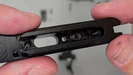
11:32 reinsert the safety catch dowel spring and detent ball. Use lithium grease to ensure a slick movement.
Safety dowel being located
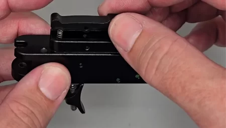
12:30 replace the trigger unit assembly and trigger guard onto the breech block using a 3mm allen key.
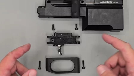
Trigger unit being positioned
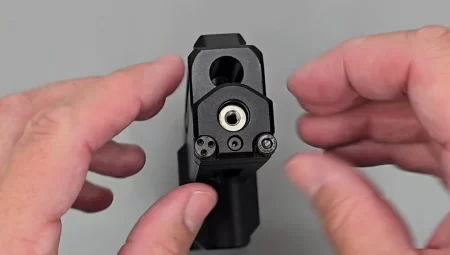
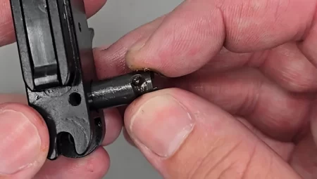
VALVE ASSEMBLY
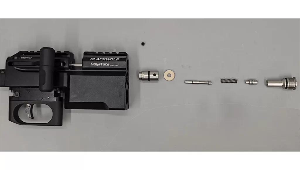
Blackwolf valve assembly
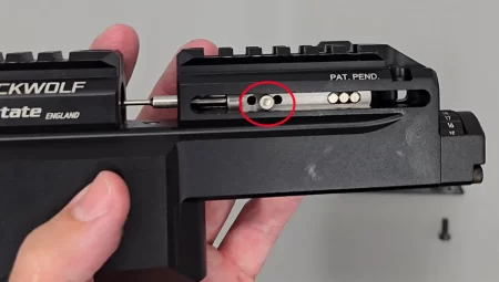
14:40 Lubricate with silicone grease and insert the valve body into the breech block with transfer port hole uppermost. Reinstall the locking grub screw into the threaded hole in the magazine well. Tighten using a 2.5mm allen key.
Inserting the valve with port uppermost
17:17 Lubricate with silicone grease and replace the valve seat with O-ring innermost. Replace the valve pin into the valve seal.
Valve seal reinsertion
18:27 on sub 12 ft/lbs versions the rear of the valve is separate reinsert this with the valve spring into the valve cap and screw into the breech block.
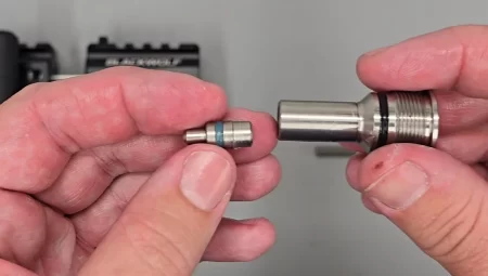
Lower powered guns the valve is 3 piece
A full regulator service video is available here
REGULATOR
The Huma-Air Regulator fitted to Blackwolf

Belvill stack order inside the regulator

The Blackwolf is fitted with the latest Huma-Air regulator that is the identical unit fitted to the BRK Ghost. The regulator should be capable of 20,000 shots or 3 years between services.
A full regulator service video is available here.
BOTTLE/CYLINDER HOUSING ASSEMBLY

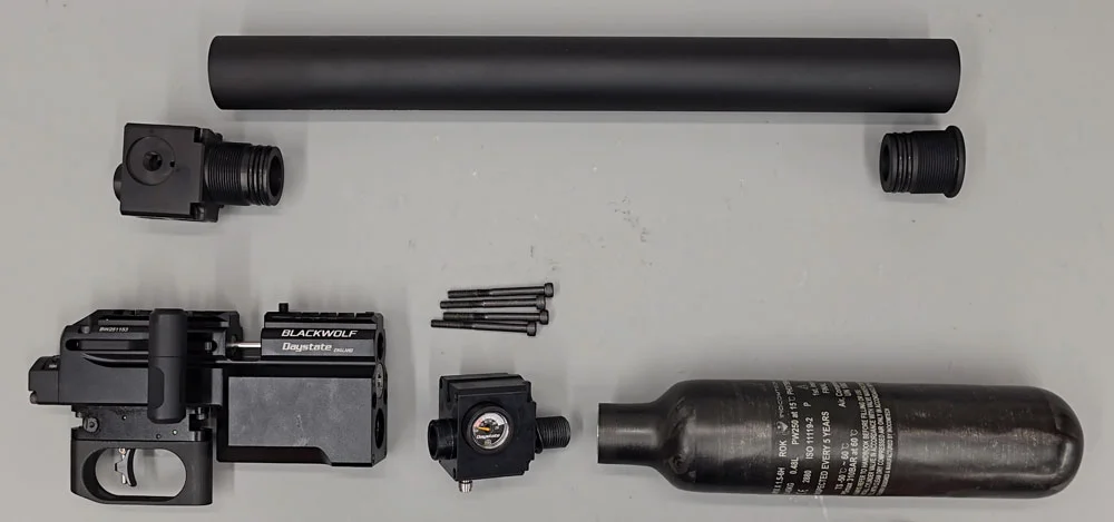
Breechblock and housings. Blackwolf can be fitted with either an air cylinder or air bottle
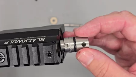
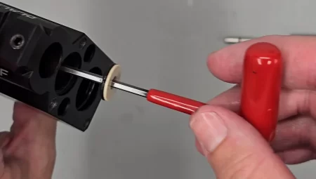
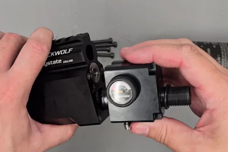
22:05 Insert the regulator back into the housing .
Replace the two gauges with the Daystate marked gauge on the left side ensure the o-ring below the gauge is in place and in good condition.
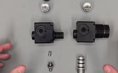
housing assembly’s
Replace the foster filling connector tightening with a 10mm deep socket.
INSTALLING THE HOUSING
Housing assemblies

BOTTLE ASSEMBLY
25:40 Using silicone grease, on the inserted bottle housing o-ring, mate the bottle housing and breechblock together. Replace and tighten the 4 screws using a 3mm allen key.
Replacing the bottle housing
Add more grease the bottle seal and without damaging the seal screw in place the bottle. Hand tight is sufficient.
CYLINDER ASSEMBLY
The same process is as for the bottle assembly but with an additional end-plug that must be greased using a silicone-based grease before inserting into the end of the cylinder.
BARREL AND BARREL SHROUD ASSEMBLY
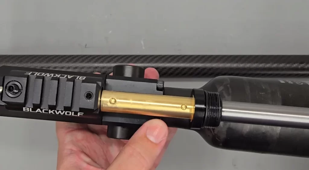
Correct orientation for barrel replacement
26:48 If the Barrel shroud has been removed from the barrel first replaced the barrel shroud retainer onto the brass collar, aligning with previous dimple marks. Tighten the single retaining screw with a 2mm allen key.
28:02 Replace the barrel with the two recesses uppermost. Grease the brass section to aid insertion over the o-rings retained inside the block and to reduce the chance of galvanic corrosion – aiding future barrel removal. Tighten the two barrel retaining screws using a 3mm allen key and checking the barrel is correctly aligned. Leave a small gap between the shroud support and block (28:39). Screw on the shroud assembly. Should a carbon tensioner be fitted at this point we recommend watching this video. Note: If a tensioner is already factory-fitted e.g. Walnut, Laminate or TAC stock versions, the tensioner is bonded in place and we do not recommend its adjustment or removal.
FINAL CHECKS AND SETTINGS
29:23 The rifle should now be refilled with air, Checking for any air leaks. The regulator can now be reset to its original position, by carefully unscrewing the regulator adjustment screw, this should be done very slowly and very carefully allowing the regulator to settle. maybe by firing a couple of dry air shots as the correct pressure is neared, as if the regulators is turned too far out air will need to be removed from the rifle to reduce the regulator pressure. A list of suggested regulator pressures is contained at the beginning of this instruction.
STOCK AND SAFETY CATCH REPLACEMENT
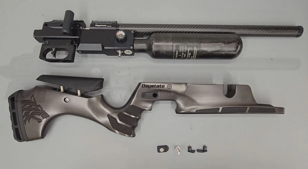
Stock components
Replace the stock and secure the 8mm stock bolt with a 5mm allen key.
30:47 Replace the safety catches of both sides of the rifle using a 2mm allen key (T10 TORX up to July 2025). Ensure the spacer on each side is also in position.
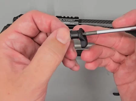
Safety assembly