THE AIR RANGER
Disassembly Guide

ON THIS PAGE
- Tools you will need
- Making the rifle safe to work on
- Removing the stock and degassing the rifle
- removing and disassembling the shroud
- separating the top and bottom halves of the block
- disassembling the top block
- removing the bottle and disassembling the housing
- disassembling the trigger
- removing the safety and hammer assembly
- disassembling the safety
- disassembling the slingshot hammer
INTRODUCTION
Daystate air rifles are engineered to the highest standards, but like anything else, they require repairs and servicing work to be carried out both in and out of warranty.
The aim of this guide and the accompanying video is to help you undertake work on the Daystate Air Ranger to address common faults.
Compressed air is dangerous. You should only use this guide if you are a qualified and experienced gunsmith used to working with compressed air. Before you carry out any work on the Daystate Air Ranger, or any PCP air rifle for that matter, you must ensure it is not cocked, not loaded and empty of air.


HISTORY
Air Ranger production started in 2004 and concluded in 2016. Two clear types were made: a regulated model up to 2007 and a later version fitted with the slingshot hammer system and Harper valve. This version was continued for the remainder of its production. These two types can be distinguished not only by the absence of stainless steel regulator in the front bottle housing, but by concurrent change to stock design, the early stocks having an integral wooden trigger guard, and later versions with a metal trigger guard fitted to an extended trigger block. In 2004 a version of the Air Ranger was also manufactured for RUAG Ammotec and branded as the RWS 500S. In 2010 there was also a highly collectible Limited Edition version titled the Red Ranger.
TOOLS YOU WILL NEED
- Allen keys: 2mm; 2.5mm; 3mm; 4mm; 5mm
- T10 TORX bit (up to July 2025 assembly)
- 10mm Deep socket
- Daystate Regulator removal tool
- Daystate Valve removal tool
- 16mm thin open-end spanner
- 22mm open-end spanner
- Tweezers
- 3-pin M5 A/T removal tool (large)- available from Daystate part number DANTITOOLXX
- Digital callipers
- O-rings used in Air-Ranger (available as a kit from Daystate)
- O-ring pick
MAKING THE RIFLE SAFE TO WORK ON
01:25 Cock the rifle and remove the magazine/single shot loader from the breech. Close the bolt and dry fire the rifle into a safe direction.
REMOVING THE STOCK AND DEGASSING THE RIFLE
01:48 Remove the fill valve cover on the underside of the rifle.
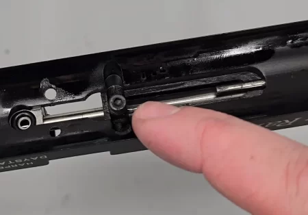
01:53 Loosen the stock bolt in the underside of the rifle using a 3/16 allen key.
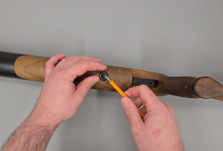
Removing the stock bolt
02:25 All air can be removed from the rifle using the Daystate de-gassing tool by attaching the quick fitting over the fill valve then screwing the tool into de-press the one-way valve until you hear air escaping. Ensure the rifle is empty of air by looking at the fill pressure gauge and dry-firing the rifle.
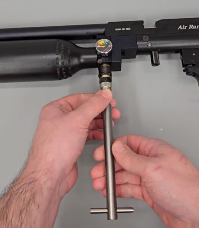
Using the Daystate bleed tool to remove all the air
03:14 If you do not have the Daystate de-gassing tool, you can use a 22mm spanner to crack open the fill pressure gauge to enable air to leak. Again, check the fill pressure gauge and dry fire the rifle to ensure it is completely empty.
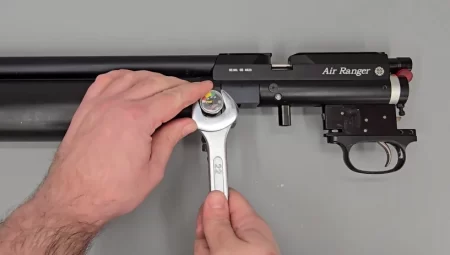
Using a 22mm spanner to remove air via the pressure gauge
REMOVING AND DISASSEMBLING THE SHROUD
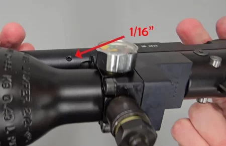
03:45 Remove the barrel band by loosening the three securing grub screws using a 1/16 allen key.
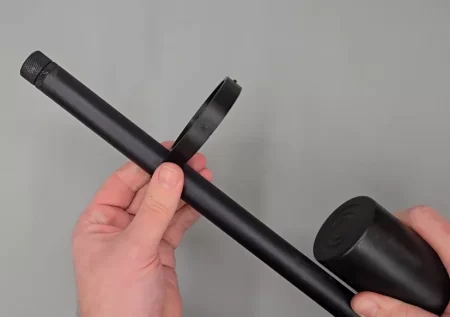
Removing the barrel support – where fitted
4:03 With the grub screws removed, slide off the barrel band off the front of the bottle then over the muzzle.
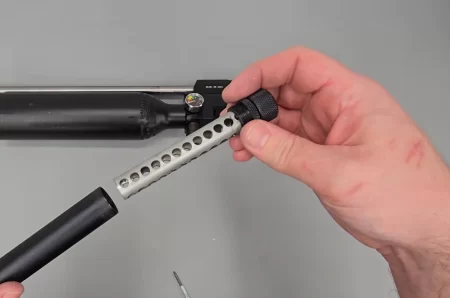
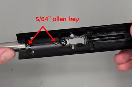
04:19 Remove the shroud body by loosening the two securing grub screws at the base of the shroud using a 5/64 allen key.
Shroud removal
04:34 With both grub screws loose, the shroud slides off the barrel.
04:48 The shroud can be further disassembled by unscrewing the barrel-end ½” BSP retainer. Note: these are likely to be done up tightly at the factory. You can then remove the baffles from the end of the shroud.
05:07 The final internal component to the shroud can be pushed out using a pellet rod or similar inserted from the muzzle end.
Removing the internals of the shroud is not usually necessary
SEPARATING THE TOP AND BOTTOM HALVES OF THE BLOCK
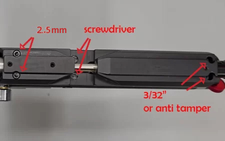
05:42 Loosen and remove the six securing screws on the top of the block. The screws at the front are M3 metric that are removed with a 2.5mm allen key.
05:59 The two middle (4BA) screws are removed with a flat bladed screwdriver.
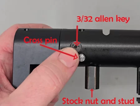
06:10 On 12 ft/lbs rifles the rear two screws are anti-tamper screws, the removal of which requires a Daystate anti-tamper screw removal tool. The rifle in the video has had these screws removed and replaced with 4BA allen bolts requiring a 3/32 allen key to remove.
06:45 With all the screws loose, the top block can be lifted off the bottom half of the block.
DISASSEMBLIKNG THE TOP BLOCK
07:06 Turn the block over and push all six retaining bolts free.
07:13 Take care to not lose the magazine indexing plate and transfer port. Pull the magazine indexing plate back to release the transfer port. The magazine indexing plate can be pulled free with a set of tweezers.
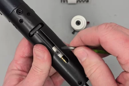
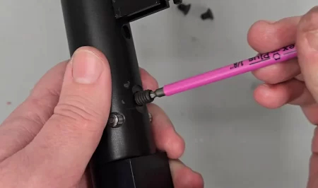
07:55 To remove the cocking bolt and pellet probe, remove the securing grub screw on top of the block just forward of the bolt using a 5/64 allen key.
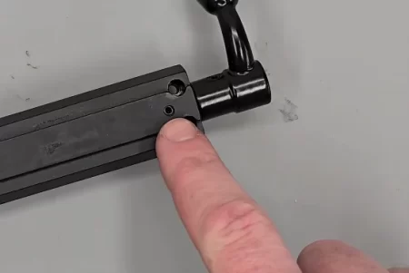
Breech bolt indent screw, spring and ball bearing
08:07 Remove the small spring and ball bearing under the grub screw using a magnet.
08:22 Remove the cocking pin (dog) on the underside of the block using a 3/32 allen key. It is fixed in place with blue Loctite from the factory, so it should be tight.
Cocking dog should be secured with locktite
08:43 The cocking bolt and pellet probe ca n be pulled free from the rear of the block.
08:56 Remove the plunger from the rear of the block using a pair of tweezers.
09:08 A spring at the very back of the block can be removed by using a magnet to manoeuvre it through the open slot.
09:19 The barrel can be removed from the top block by loosening the two all bolts on the top of the block using a 5/64 allen key.
09:31 Two further allen screws are removed from the underside of the top block using a 5/64 allen key. This will allow the barrel to pull free. Note: the two longer grub screws are the ones from the top of the block. The two shorter grub screws are the ones from the bottom of the block.
The barrel is retained with 4 screws, two at the top and 2 underneath
10:03 See video for additional information on ‘o’ rings and leak symptoms.
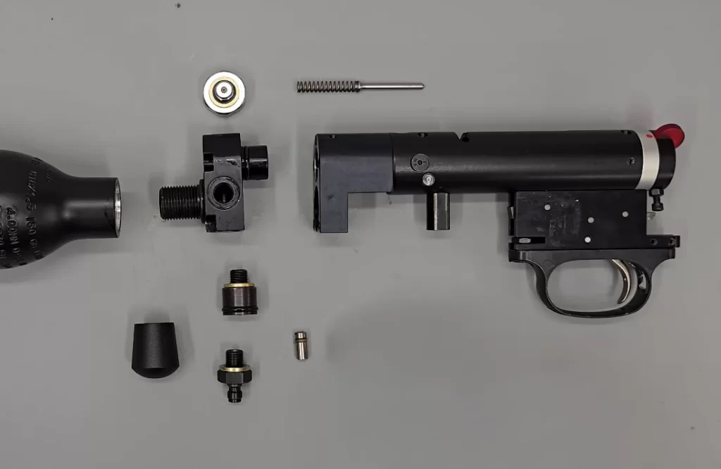
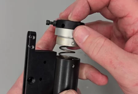
REMOVING THE BOTTLE AND DISASSEMBLING THE HOUSING
Title picture
12:07 The air bottle unscrews from the bottle housing by hand. It may be necessary to put the block into a vice with jaw protection.
12:43 The five securing bolts on the front of the bottle housing can be loosened using a 5/32 allen key. Note that the valve return spring is under the cap and will push forward when all the screws are loosened.
Removing the bottle housing
13:10 With the screws removed, the bottle housing can be removed.
13:14 The valve inside the main block can be removed using a pair of tweezers.
Remove the valve and spring. earlier rifles used a larger valve and no valve seat
13:54 The pressure gauge can be removed from the bottle housing using a 22mm spanner.
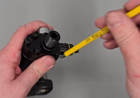
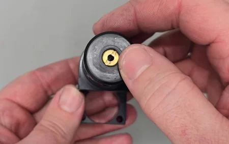
14:07 Remove the Foster fitting using a 16mm spanner.
14:48 Remove the foster fitting. It can be separated from the spacer by clamping the spacer in a soft jaw vice to unscrew the foster fitting with a 16mm spanner. This will expose a one-way valve plunger in the base of the fitting.
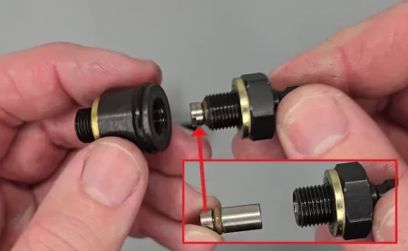
Foster fitting assembly dismantled
15:05 See video for additional information on ‘o-rings and leak symptoms.
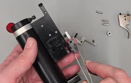
DISASSEMBLING THE TRIGGER

Trigger arrangement
18:28 The trigger guard is removed by loosening the two screws at the front and back of the trigger guard using a flat bladed screwdriver. Ensure the retaining nut behind the forward-most screw is not lost.
18:56 Remove the spacer at the bottom of the trigger assembly by removing the screw using a 3/32 allen key.
Later Air Rangers had a spacer
19:07 With the screw removed, use a set of needle-nosed pliers to pull the spacer free from the trigger block.
19:19 Remove the rearmost of three pins from the trigger block using a small punch or similar. This will release the trigger blade. Ensure you do not lose the small spring at the top of the trigger.

Removing the trigger blade
19:38 Remove the middle pin to remove the sear, taking care again to not lose the spring behind the sear.
19:51 The final, forward-most pin can be removed to release a second sear and spring.
Removing the front sear, note the spring
REMOVING THE SAFETY AND HAMMER ASSEMBLY
Full assembly
20:41 Use a 1/16 allen key and undo the two securing grub screws forward of the safety. Keep a firm grip on the safety as it will be under pressure from the hammer spring.
Safety assembly removal
21:10 With the safety removed, the hammer spring and anti-rattle guide can also be removed.
CAUTION the safety directly holds back the hammer spring!
21:19 Remove the screw in the slot in the top of the block using a 3/32 allen key. This will allow the slingshot hammer to be removed.
This screw needs to be removed for access to the hammer.
DISASSEMBLING THE SAFETY
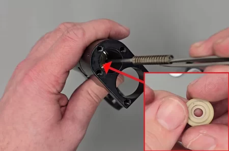
21:40 Remove the spring detent by loosening the grub screw on the safety end cap using a 1/16 allen key.
21:50 Remove the small spring and ball bearing behind the grub screw using a magnet.
22:04 Separate the two halved of the safety using a flat headed screwdriver to undo the middle screw. Note: this will be held in place with Loctite at the factory.
22:30 The safety screw simply undoes by first loosening the locking nut with a 1/4 spanner and then unscrewing the screw. Note that 12 ft/lbs will be fitted with an anti-tamper pin that will require a Daystate anti-tamper removal tool to remove.
DISASSEMBLING THE SLINGSHOT HAMMER
23:16 Rotate the brass component to expose the small grub screw in the hole in the side. Remove the screw with a 2mm allen key.
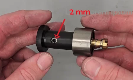
Hammer adjuster locking screw
23:35 Use a long M4 bolt and screw into the hole exposed by removing the grub screw.
23:44 Use a flat bladed screwdriver to undo and remove the brass component. Note: red Loctite will have been applied to the brass component.
24:04 Remove the M4 bolt and slide the hammer weight out.
24:15 The striking face can be removed using a 3mm allen key.
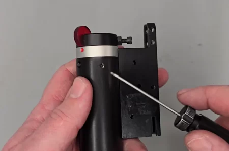
REMOVING THE VALVE HOUSING
24:49 Remove the two securing screws using a 3/32 allen key.
Rear housing (A) screws
25:03 Remove the stock bolt fitting using an adjustable spanner.
25:13 Remove the screw underneath using a 1/8 allen key.
Remove this screw to separate the body
25:22 Knock out the pin by clamping the action in a vice with soft jaw protection and knock the pin through using a 4mm punch.
25:53 Remove the ‘o’ ring at the top of the action and pull the two pieces apart.
26:12 The brass cap valve stem seal retaining screw can be removed using a flat-headed screwdriver to expose the valve stem seal. Note: this will be factory set and Loctite in position. It is recommended that this seal and screw only be disturbed if there is a problem with the seal leaking.
It’s rare for this seal to need replacing