THE AIR RANGER
Assembly Guide

ON THIS PAGE
- Tools you will need
- Installing The Valve Housing
- Assembling The Hammer
- Assembling The Safety
- Installing The Bottle Housing and Valve Assemblies
- Installing The Trigger
- Assembling The Bottle Housing
- Installing The Bottle Housing and Valve
- Assembling The Top Block
- Mating the Block Halves
- Adjusting The Saftey
- Installing The Shroud
- Installing The Stock
INTRODUCTION
Daystate air rifles are engineered to the highest standards, but like anything else, they require repairs and servicing work to be carried out both in and out of warranty.
The aim of this guide and the accompanying video is to help you undertake work on the Daystate Air Ranger to address common faults.
Compressed air is dangerous. You should only use this guide if you are a qualified and experienced gunsmith used to working with compressed air. Before you carry out any work on the Daystate Air Ranger, or any PCP air rifle for that matter, you must ensure it is not cocked, not loaded and empty of air.

TOOLS YOU WILL NEED
- Allen keys: 2mm and 3mm. 1/16, 1/8, 3/32, 5/64, 3/16 and 5/16
- 16mm and 22mm spanner
- Adjustable spanner
- Triangular anti-tamper tool
- Tweezers
- 6mm and 12mm flat head screwdriver
- Magnets
INSTALLING THE VALVE HOUSING
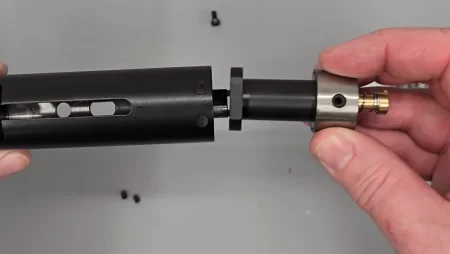
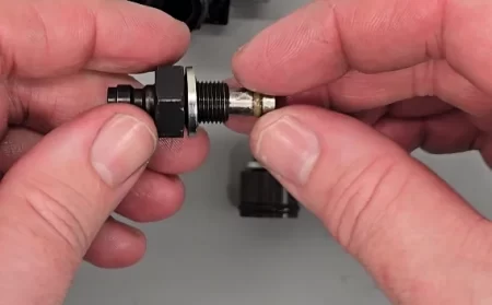
01:26 Add a small amount of silicon grease to the valve stem seal ‘o’ ring.
01:43 Drop the ‘o’ ring seal into the seat.
01:52 Take the brass coloured cap and drop on top of the seal and screw into place using a flat headed screwdriver.
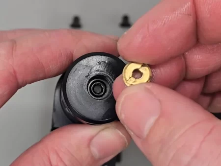
Valve oring reassembly
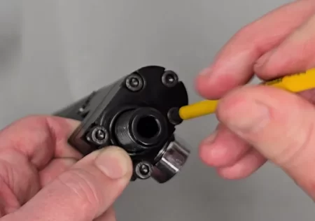
02:02 Align the valve housing with the main block.
02:12 Insert the two counter sunk screws into the sides of the valve housing/block – one either side – using a 3/32 allen key. Tighten the screws and then back off a quarter turn.
02:45 Insert the grub screw to the bottom of the main block and tighten using a 1/8 allen key.
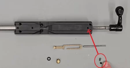
03:03 Insert the pin to the hole underneath the screw on the right-hand side and drive through by inserting into a vice until an equal amount of the in is visible from both sides.
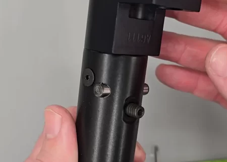
Replacing the screws and crosspin before tightening the screws
03:23 Attach the stock bolt fitting, tightening with an adjustable spanner.
03:33 Fully tighten the two side screws using a 3/32 allen key.
ASSEMBLING THE HAMMER
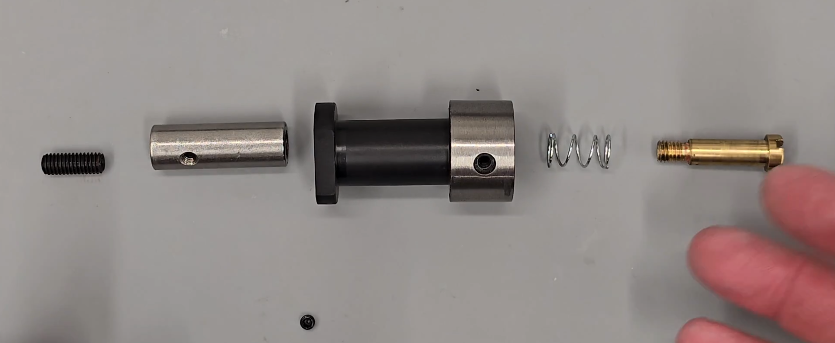
03:52 Take the hammer weight and screw in the hammer striker ensuring the flat front of the striker faces the front of the hammer (the end closest to the small hole). Tighten with a 3mm allen key through the back of the hammer weight.
04:39 Insert the hammer wight into the hammer housing, aligning the hole in the side of the weight with the hole into the side of the housing. (04:49) Use an M4 screw and screw through the two aligned holes.
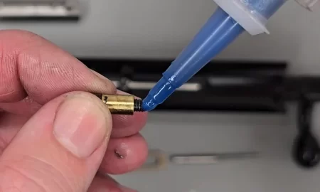
04:59 Take the brass retention piece and place the return spring over it.
05:06 Add a small amount of blue Loctite to the thread then screw into the back of the hammer weight, tightening with a flat blade screwdriver. The M4 bolt can now be removed.
05:36 Insert the locking grub screw into the side hole and tighten using a 2mm allen key.
ASSEMBLING THE SAFETY
Hold the safety against spring tension
07:15 Add a light coat of lithium grease to the front of the safety body.
07:25 Take the back section and fit to the safety housing aligning the pin at the top with the indent.
07:40 Apply a small amount of blue Loctite to the thread on the central screw. Insert into the middle of the safety housing and tighten using a flat head screwdriver.
08:12 Apply a small amount of lithium grease to the small spring and ball bearing. Drop the ball bearing into the hole to the left of the rear of the safety.
08:30 Drop the spring on top of the ball bearing. (08:40) Secure with the small grub screw, tightening with a 1/16 allen key.
08:53 Screw the safety screw into the hole in the side of the safety housing.
INSTALLING THE BOTTLE HOUSING AND VALVE ASSEMBLIES
09:30 Insert the hammer into the main block black part first, aligning the hole in the silver component with the top of the block, and push into the block, ensuring the hole aligns with the slot. (09:55) Secure with the screw, tightening with 3/32 allen key.
Replace the hammet with the screw hole uppermost
10:04 Insert the hammer spring and anti-rattle guide to the block.
10:10 Top off with the safety assembly. Push against the hammer spring, ensuring the screw holes are aligned with the holes in the sides of the block.
Hold the safety against spring tension
10:35 Secure using the two grub screws in the two outer holes and tighten.
INSTALLING THE TRIGGER
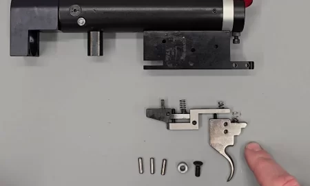
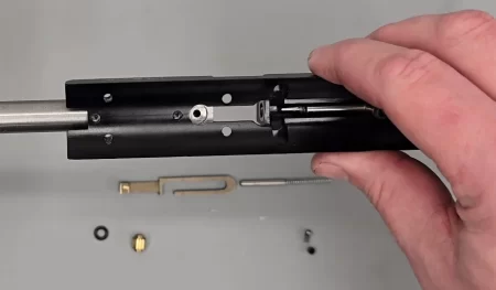
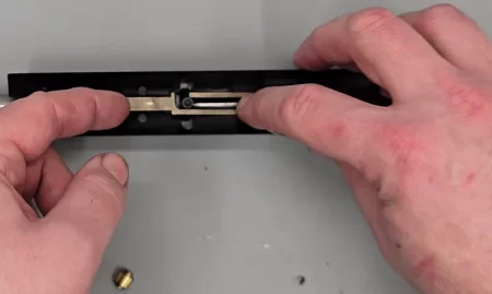
Trigger mechanism
11:27 Insert the front sear into the front of the trigger block. Secure with a pin. You may find using a pair of tweezers or similar will help align the holes in the sear and the trigger block so you can push the pin home (11:52).
12:00 The hole in the second sear must align with the middle hole in the trigger block. Again, using a pair of tweezers or similar will help you align the holes in the sear and block so you can push the pin home (12:20).
12:34 The top of two holes at the top of the trigger blade must align with the rearmost hole in the trigger block. Secure with a pin.
13:06 Insert the spacer into the bottom of the trigger block, aligning with the hole forward of the trigger blade. Secure with the retaining screw and tighten using a 3/32 allen key.
Early rifles did not have this spacer
13:44 Secure the trigger guard by inserting the nut into the slot at the front of the trigger guard, placing the trigger guard on top and then securing with the screw and tightening with a flat head screwdriver. Repeat for the smaller back screw and disc.
ASSEMBLING THE BOTTLE HOUSING
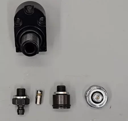
Bottle-housing-assembly
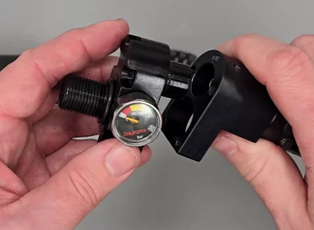
15:04 Screw the fill pressure gauge into the side of the bottle housing and tighten with a 22mm spanner.
replacing the gauge note the douty seal
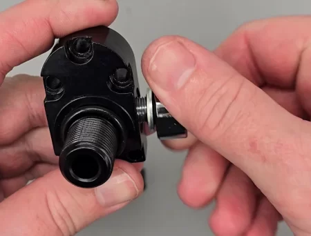
15:09 Insert the one-way valve into the foster fitting then screw the rear component on.
Replacing the filling valve piston. just removing this and cleaning cures most filling leaks
15:34 Screw into the bottom of the bottle housing, tightening with a 16mm spanner.
INSTALLING THE BOTTLE HOUSING AND VALVE
16:36 Apply a light coat of silicon grease to the valve seat ‘o’ ring and then drop into the top hole of the main block body ensuring the counterbored end faces out.
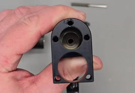
Valve seal in place
17:02 Insert the valve pin and valve return spring and drop on the valve seat with the spring end uppermost.
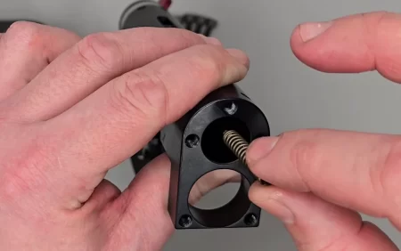
Take care when replacing valve not to damage seal
17:14 The bottle housing can then be pushed into the bottom hole of the front of the main block having first applied a small amount of silicon grease to the ‘o’ ring.
Joining the hosing with body. this seal is a known leak point so o-ring replacement is essential
17:35 Insert the five M5x27mm (including head) bolts into the holes in the bottle housing and tighten with a 3 mm allen key.
Daystate recommend to replace the Alloy bottle, screws and housing every 10 years
17:48 The air bottle can be screwed on having first applied a small amount of silicon grease to the ‘o’ ring at the base of the thread.
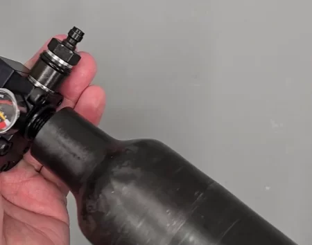
Screw in place the bottle, this only needs to be hand tight
ASSEMBLING THE TOP BLOCK
19:47 Apply a light coat of moly grease to the pellet probe.
20:10 Insert the probe through the back of the top block.
20:19 Apply a small amount of blue Loctite to the thread on the cocking dog and screw into the hole in the bottom of the pellet probe accessed via the slot on the underside of the top block. Tighten with a 3/32 allen key.
The cocking dog (bolt retaining pin) should be locktited
21:00 Slide the barrel into the front of the block aligning the transfer port in the barrel with the bottom of the block and the dimples int the barrel with the two holes at the front of the block.
Replacing the barrel and aligning the screw holes
21:23 Insert the shot grub screws into the bottom of the block, and the longer grub screws into the top of the block.
21:41 Apply a small amount of moly grease to the ball bearing and drop into the hole at the top of the rear of the block just forward of the cocking bolt.
21:53 Add a small amount of moly grease to the spring and then drop into the hole over the ball bearing.
22:02 Secure by placing the grub screw on top and tighten
bolt detent ball and spring only needs to be lightly tightened
22:39 Apply a small amount of moly grease to the spring and insert onto the hole at the rear of the underside of the block and slide towards to the cocking bolt.
22:50 Apply a small amount of moly grease to the pin and slide that into the spring.
23:03 Apply a small amount of moly grease to the internal surfaces of the block using a cotton bud or similar.
23:27 Apply a small coating of moly grease to the magazine indexing plate.
23:44 Place the magazine indexing plate over the cocking dog so the flat side faces the bottom of the block and push back against spring tension.
replacing the magazine indexing arm
24:12 Apply a small amount of silicon grease to the transfer port ‘o’ ring.
24:20 Pulling the cocking bolt back to pull the magazine indexing plate back and drop the transfer pot ‘o’ ring over the transfer port hole then place the brass transfer port piece.
replace the transfer port
MATING THE BLOCK HALVES
24:46 Add a small amount of silicon grease to the second transfer port ‘o’ ring and locate on the transfer port at the top of the lower block.
Dont forget the second transfer port oring
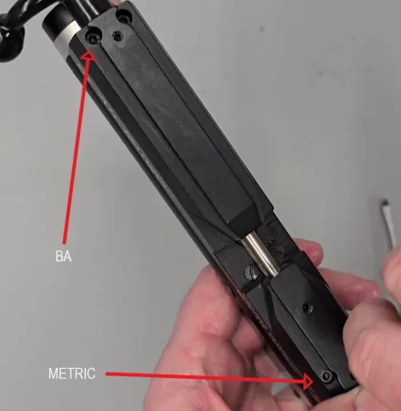
25:06 Take the top block and align it with the bottom block and secure with the six bolts# through the top block and tighten. Note that the rear bolts on 12 ft/lbs rifles are likely to be anti-tamper bolts and for all export rifles 4BA x 3/4″ requiring a 3/32″ allen key.
25:40 The two shorter slotted bolts are inserted in the holes in the bottom of the breech and tightened with a flat head screwdriver.
25:50 The final M3 allen headed bolts are inserted to the two holes at the front of the top block and tighten with a 2mm allen key.
front and rear screws are not interchangable
ADJUSTING THE SAFETY
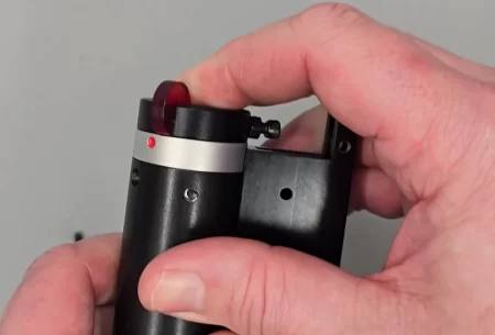
26:30 Adjust the safety screw until it prevents the trigger firing when the safety catch is in the ‘fire’ position. (24:54) When satisfied the screw is in the correct position, hold the screw and tighten the nut against the safety block using a ¼ spanner.
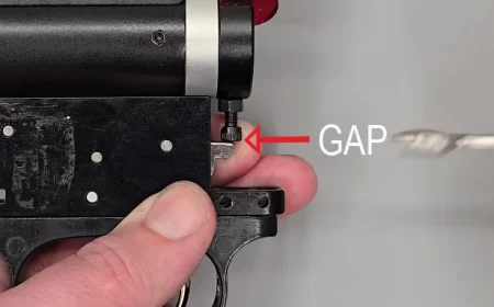
Adjust the safety screw
INSTALLING THE SHROUD
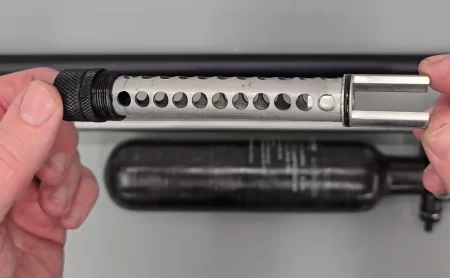
Baffle assembly
27:49 Apply a small amount of silicon grease to the rear ‘o’ ring of the baffle assembly and then insert into the end of the shroud and screw tight.
28:07 Check the two grub screws at the back of the shroud are wound out and slide the shroud assembly over the barrel with the two grub screws facing downwards.
28:36 Tighten the two grub screws using a 5.64 allen key.
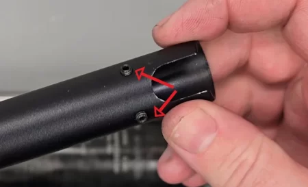
Screws are on the underside of the scroud. early rifles just had the one
