THE WOLVERINE R
Disassembly Guide


In addition, a separate regulator service video is available here
INTRODUCTION
Daystate air rifles are engineered to the highest standards, but like anything else, they require repairs and servicing work to be carried out both in and out of warranty.
The aim of this guide and the accompanying video is to provide instruction on how to disassemble the Daystate Wolverine R.
This guide and video applies to:
- Wolverine R (all models)
- Wolverine
- Wolverine 2
Compressed air is dangerous. You should only use this guide if you are a qualified and experienced gunsmith used to working with compressed air. Before you carry out any work on the Daystate Wolverine, or any PCP air rifle for that matter, you must ensure it is not cocked, not loaded and empty of air.
HISTORY
The Daystate Wolverine probably has the longest development cycle of any Daystate rifle starting as a project in 2006 before its eventual launch as a production rifle in 2012. The first version was the Wolverine 303 a .30 calber 100 foot pounds airgun. Subsequent developments took this to a 12 ft/lbs or 30 ft/lbs version a year later which were then offered in a cylinder and bottle types by the clever use of a removable forend piece. The Wolverine marks a move away from a classic cylinder base to a modern block design where all components are inserted into a housing rather than being contained in a tube. The Wolverine mark 2 incorporated changes to the valving as well as revisions to the breach block and improved stock. In 2017 The Wolverine R (the model here) was launched incorporating as standard a HUMA-Air regulator, new stock and incorporated a pulsar style breach block.


TOOLS YOU WILL NEED (0:24)
- Allen keys: 0.89mm; 1.5mm; 2mm; 2.5mm; 3mm; 4mm; 5mm
- Open end spanners: 11mm, 22mm
- 5/8 ring spanner
- 3 pin M5 A/T removal tool (large)- available from Daystate part number DANTITOOLXX
- 3 pin M3 A/T removal tool (small)- available from Daystate part number DANTITOOLWL
- Tweezers
- Flat blade screwdriver
- 3mm and 6mm wide Daystate degassing tool
- Parrot grips / large pliers
- Digital callipers
O rings used in Wolverine R
| Wolverine R | Size | IMP or Metric | Shure | Location | |
|---|---|---|---|---|---|
| 1 | 2 x 1.5 | M | N70 | 0.22 | |
| 3 | 017 | IMP | N70 | ||
| 1 | 006 | IMP | N70 | Striker valve seal | |
| 5 | 19.5 x 1.5 | M | N70 | Valve core | |
| 4 | 122 | IMP | N90 | ||
| 2 | 18 | IMP | N70 | ||
| 1 | 617 | IMP | N70 | ||
| 1 | 006 | IMP | Urethane | ||
| 1 | 111 | IMP | N70 | ||
| 1 | 7.1 x 1.6 | M | N70 | 0.30 | |
| 1 | 4 x 1.5 | M | N70 | .177 | |
| 1 | 5 x 1.5 | M | N70 | .25 | |
| 1 | 6 x 1.5 | M | N70 | .25 | |
| 2 | 10 x 1 | M | N70 | ||
| 2 | 12 x 1 | M | N70 | ||
| 1 | 111 | IMP | Urethane | ||
| 1 | 14 x 2 | M |
REMOVING THE STOCK AND DE-GASSING
Removing the stock will make it easier to work on the rifle (and prevent any damage to it). You will need to de-gas the rifle to work on it safely.
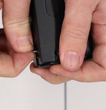
1:05 The stock is removed by undoing an Allen bolt on the underside of the stock using a 5mm Allen key
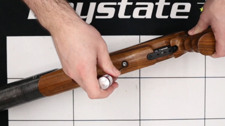
The stock is removed by undoing a single Allen bolt
1:30 Use the Daystate de-gassing tool to attach to the fill valve and bleed the main air supply, remembering to note down the current regulator pressure – you may need that later.
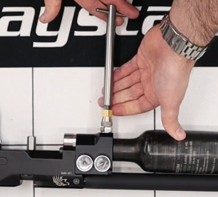
Daystate de-gassing tool to attach to the fill valve
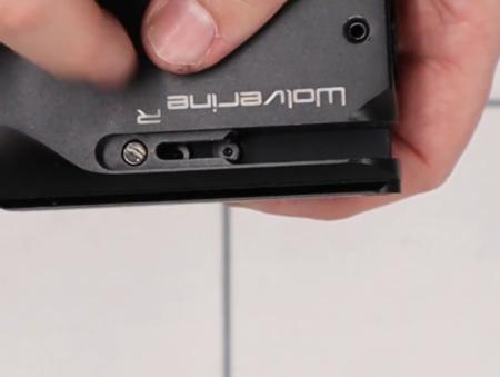
Note that on rifles fitted with a regulator (designated Wolverine R), you may need to ensure the regulator chamber is emptied of air as well (2:14). The rear-most gauge will indicate regulator chamber air pressure. To remove remaining air, either dry fire the rifle until empty or loosen the regulator pressure gauge slightly.
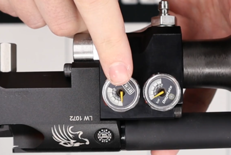
The rear-most gauge will indicate regulator chamber air pressure
2:50 To ensure the rifle is fully safe and empty of air, remove both the air fill pressure and regulator pressure gauges using a 22mm spanner.
REMOVING THE SHROUD AND BARREL
Removing the barrel will give you access to the breech seal ‘o’ ring and to two other ‘o’ rings inside the breech block that seal the transfer port.
Removing the barrel will give you access to the breech seal ‘o’ ring and to two other ‘o’ rings
3:16 The shroud can be unscrewed by hand. Note that it is not necessary to remove the shroud in order to remove the barrel.
3:27 Remove the shroud carrier by loosening two grub screws using a 2mm Alen key.
3:40 Remove the barrel by loosening two screws located on top of the rifle just forward of the breech with a 2.5mm Allen key. If necessary, you can remove the back boss using a 2mm Allen key (3:57) to loosen the grub screws.
REMOVE AIR BOTTLE
Note: it is imperative that you have followed steps to de-gas the rifle.
4:29 The air bottle is simply unscrewed by hand from the action.
FRONT ASSEMBLY
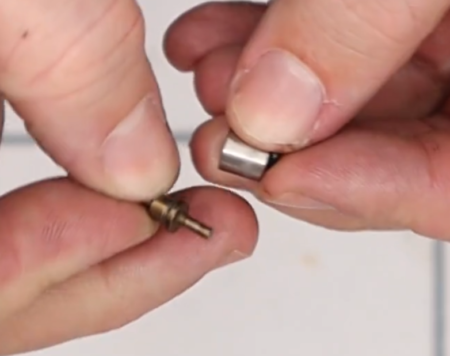
4:50 The foster fitting and one way valve is removed by using a 5/8 ring spanner. The one-way plunger can be removed from the cavity using a pair of tweezers. The brass cup used to seat the plunger will fall out.
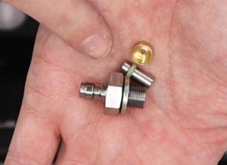
Foster fitting assemble dismantled
5:30 Remove the front block and valve pin/spring
Sub 12 ft/lbs Wolverine air rifles are fitted with an anti-tamper screw. You will need an anti-tamper removal tool (large) to remove the screw (5:37). The front block is removed from the main block using a 4mm Allen key to undo three screws (6:29). Take care when pulling the front block away from the main block as the valve spring will remain inside the main block. The valve spring and plastic housing can be removed by hand (6:55).
The valve and valve seat can be removed from the main block using a pair of tweezers (7:05).
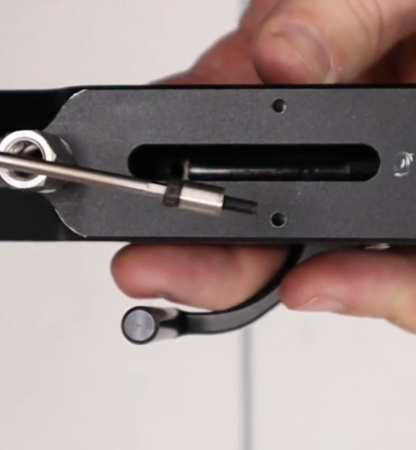
7:26 A stem spring retainer is fitted to 12 ft/lbs rifle only and can be removed by inserting a small bar (Allen key or similar) into the hole and turning. This will allow you to remove the volume reducer (also only fitted to 12 ft/lbs rifles (7:40).
REGULATOR
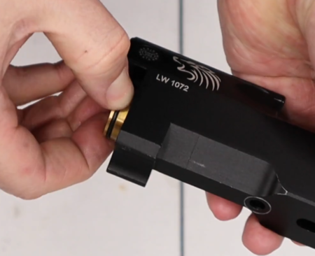
7:45 The regulator is removed from the front block using a pair of parrot grips.
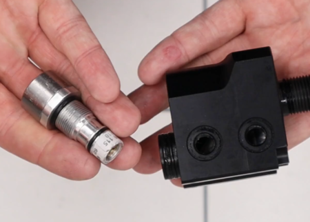
Regulator removed
You will need to measure the distance between the adjustment screw and the top of the housing using a pair of digital callipers (8:13). This will enable you to set the regulator pressure at its original level when reassembling the regulator.
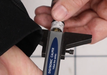
Measure the distance between the adjustment screw and the top of the housing
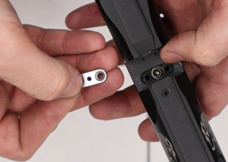
Disassembling the regulator is achieved by first removing the top cap (8:33) using a 22mm spanner and parrot grips. This will reveal the regulator piston (8:47) that can be removed by inserting one of the bolts used to hold the front block to the main block (8:50). Remove the small white sealing disc. The adjustment screw can be removed using a flat blade screwdriver (9:18).
A separate regulator service video is available here
REMOVING THE TRIGGER
Note: ensure the rifle is not cocked before removing the trigger.
9:47 Remove the four bolts at the base of the trigger assembly using a 2mm Allen key. Take care to not lose a small spring in the trigger assembly.
Take care to not lose a small spring in the trigger assembly
Use a small flat bladed screwdriver the remove the two screws holding on the trigger guard (10:19).
REMOVE SAFETY, HAMMER SPRING AND HAMMER
10:37 The safety is removed by first removing the three-pin anti-tamper screw using the Daystate tool (small). The Allen bolt on the other side of the block from the anti-tamper screw is removed with a 2mm Allen key. Put pressure on the safety assembly to compensate for the fact that it will be under tension from the hammer spring (11:30). Once the Allen bolt is removed, pull down the pin to enable the safety catch assembly to be removed. Take care to not lose a small ball bearing and spring.
Pull down the pin to enable the safety catch assembly to be removed
12:00 This will enable the hammer spring to be removed. In addition to the hammer spring itself, the anti-rattle guard will also come out along with a ball bearing.
12:28 Hammer disassembly. Note: it is unlikely you will ever need to disassemble to hammer, so the following is provided for information purposes.
First peel back a sticker on the left side of the main block to reveal a screw. You may have to tip the block down for the hammer to move forward. Remove the screw with a 2.5mm Allen key (12:42). This will allow the hammer to fall out of the back of the main block.
13:05 Remove the locking screw at the back of the hammer using a 2mm Allen screw. Use an M4 bolt (13:17) and screw it into the thread revealed having removed the locking screw. This will allow you to insert a 3mm Allen key into the other end of the hammer (13:25) to wind a grub screw out of the front of the hammer assembly. To separate the two halves of the hammer, use a flat blade screwdriver in the gold-coloured screw (13:47). Note that in the factory manufacturing process, Loctite is used to hold the screw in place.
REMOVING SIDELEVER AND PELLET PROBE
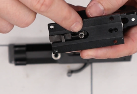
14:40 To remove the sidelever, turn the block upside down to access a screw on the pellet probe through the slot and undo it with a 2.5mm Allen key.
Remove remove pellet probe screw
Remove the screw on top of the block (14:55) using a 2.5mm Allen key to remove the side lever and pellet probe together.
The pellet probe is separated from the cocking lever by undoing a screw using a small flat blade screwdriver (15:15), taking care to not lose a small ball bearing and spring that are best removed with a set of tweezers.
The pellet probe arm can be removed from the probe by undoing a small screw (16:28).
Back on the main block, the side lever cover plate is removed by unscrewing two Allen screws with a 2mm Allen key (16:48). The screws do not need to be removed fully, simply loosened.
Loosen but do not remove cover plate screws
REMOVING INDEXING PIN AND VALVE
17:20 Remove the stop bolt on the underside of the main block using an 11mm spanner. This will expose a bolt that can be removed using a 3mm Allen key. On top of the main block, remove two screws located at the bottom of the breech using a 2mm Allen key (17:35). Note that the plate covers the magazine indexing pin and you will need to keep pressure on the plate to avoid it pinging off.
Index pin cover plate removal
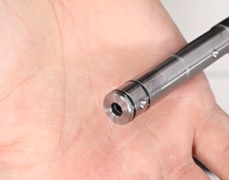
Removing the spring (17:57) gives access to the indexing pin (18:01).
Indexing pin removed
The indexing pin comprises a small ‘o’ ring in the base and the main sleeve – all of which can be taken apart without the need for any tools (18:13).
Using a long Allen key or similar inserted to the front of the main block, the valve can be pushed out (18:29) of the back of the main block.
After pushing the valve out it, can be removed from the breechblock