THE WOLVERINE R
Assembly Guide


ON THIS PAGE
- Tools you will need
- Installing indexing pin and valve
- Installing side lever cocking arm and pellet probe
- Hammer assembly
- Installing safety and hammer spring
- Installing the trigger
- Regulator assembly and installation
- Front block assembly
- Fitting the front block and valve pin/spring
- Barrel installation and shroud assembly
- Pressurising the rifle and setting power
- Fitting the action in the stock
INTRODUCTION
Daystate air rifles are engineered to the highest standards, but like anything else, they require repairs and servicing work to be carried out both in and out of warranty.
The aim of this guide and the accompanying video is to provide instruction on how to re-assemble the Daystate Wolverine R.
This guide and video applies to:
- Wolverine R (all models)
- Wolverine
- Wolverine 2
Compressed air is dangerous. You should only use this guide if you are a qualified and experienced gunsmith used to working with compressed air. Before you carry out any work on the Daystate Wolverine, or any PCP air rifle for that matter, you must ensure it is not cocked, not loaded and empty of air.
TOOLS YOU WILL NEED (0:24)
- Allen keys: 0.89mm, 1.5mm, 2mm, 2.5mm, 3mm, 4mm and 5mm
- Open ended spanners: 11mm and 22mm
- 5/8 ring spanner
- 3 pin M5 A/T removal tool (large)- available from Daystate part number DANTITOOLXX
- 3 pin M3 A/T removal tool (small)- available from Daystate part number DANTITOOLWL
- Tweezers
- Flat bladed screwdriver: 3mm wide and 6mm wide
- Parrot grips/large pliers
- Digital callipers
O rings used in Wolverine R
| Quantity | Size | British Standard or Metric Size in mm | Shore | Notes |
|---|---|---|---|---|
| 1 | 2 x 1.5 | M | N70 | .22 CAL |
| 3 | 017 | BS | N70 | |
| 1 | 006 | BS | N70 | |
| 5 | 19.5 x 1.5 | M | N70 | |
| 4 | 122 | BS | N90 | |
| 2 | 018 | BS | N70 | |
| 1 | 617 | BS | N70 | |
| 1 | 006 | BS | URATHANE | |
| 1 | 111 | BS | URATHANE | |
| 1 | 71 x 1.6 | M | N70 | .30 CAL |
| 3 | 4 x 1.5 | M | N70 | .177 CAL |
| 1 | 5 x 1.5 | M | N70 | .22 CAL |
| 2 | 10 x 1 | M | N70 | |
| 4 | 12 x 1 | M | N70 | |
| 1 | 111 | BS | N70 | |
| 1 | 14 x 2 | M | N70 |
INSTALLING VALVE AND INDEXING PIN
1:00 Lightly coat the three ‘o’ rings on the valve body with silicon grease. You will only need a small amount of grease.
1:13 Insert the valve body into the back of the block ensuring the transfer port at the top is uppermost. Push it forward until the transfer hole is visible through the bottom of the breech.
Insert the valve body into the back of the block ensuring the transfer port at the top is uppermost
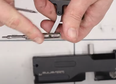
1:27 Next you will need to install the valve pin. The pin is inserted into the cup and an ‘o’ ring is placed over the shaft of the pin as it protrudes from the bottom of the cup. Apply a light covering of silicone grease to the ‘o’ ring.
Indexing pin assembly
1:45 Drop the indexing pin, ‘o’ ring end first into the indexing pin recess hole in the valve. If the pin cup does not fully seat you can insert the 3mm grub screw (1:55) into the underside of the vale in order to seat it properly. Note. On later rifles made after 2020, the indexing pin and spring are replaced with a solid blanking plug and o-ring and the later Self-Indexing magazine does not need a pin activator to function.
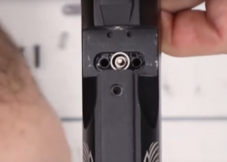
2:08 You can now replace the valve cover plate and spring at the base of the breech. The spring drops over the valve pin (2:13). The plate is then secured with two 2mm Allen screws (2:23).
Secure the valve in place
Ensure the plate is flush with the bottom of the breech. Once in place, tighten the 3mm grub screw to secure the valve in place and screw on the stop bolt nut with an 11mm spanner (2:39).
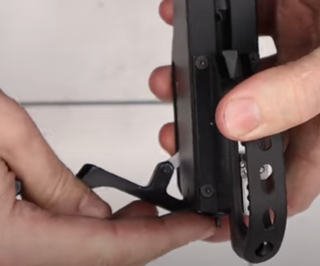
INSTALLING SIDE LEVER COCKING ARM AND PELLET PROBE
The side lever cocking arm is designed to be installed on either side of the rifle. Once you have decided which side, you will need to re-attach a blanking plate on the opposite, unused side (3:07) by tightening two 2mm Allen screws accessed through the slot on the other side (3:20).
Re-attach blanking plate
3:26 Take the small spring and ball bearing and apply a small amount of moly grease or lithium grease. The spring is inserted vertically (3:44) into the cut out in the side of the pellet probe. A pair of tweezers will make this easier.
Spring and ball bearing in the cocking linkage
3:52 Place the ball bearing on top of the spring – again a pair of tweezers helps – and push the ball bearing and spring down into the cut out.
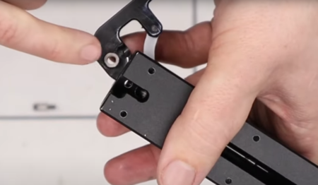
4:02 Take the pellet probe and, ensuring the linking arm is orientated slightly forwards, compress the spring and ball bearing to locate into the cocking arm. Attach by using a small flat bladed screwdriver to tighten the screw having first inserted a small amount of moly grease into the hole.
4:58 Apply a thin coat of moly grease (or lithium grease) to the pellet probe and insert the probe into the back of the main block (5:12).
Grease and re-insert into breechblock
Add a small amount of grease to both sides of the hole at the rear of the cocking arm (5:23).
The small bush
Apply some grease to the small bush as well (5:35) and insert into the hole at the rear of the cocking arm.
5:40 Push the cocking lever into the rear of the main block to align the holes so you can insert the cocking arm screw and tighten with a 3mm Allen key.
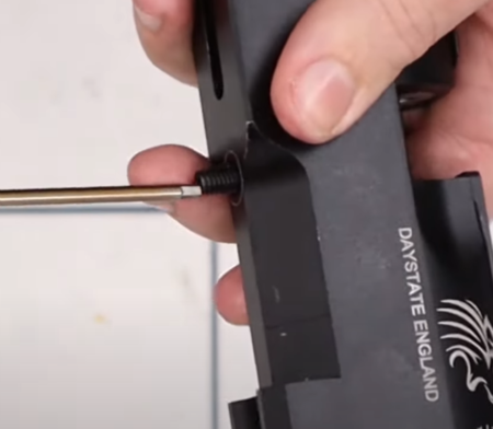
6:03 Using a 2.5mm Allen key, insert the cocking pin through the slot in the underside of the main block to screw into the front of the pellet probe. Use medium blue strength Loctite to secure the cocking pin.
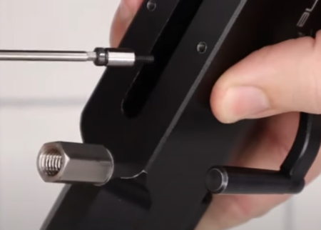
Cocking pin should be glued with thread adhesive
HAMMER ASSEMBLY
Note: It is unlikely you will need to disassemble the hammer, so the following is largely provided for information/reference.
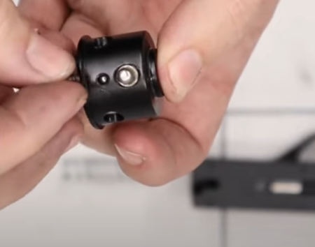
6:42 Insert the brass coloured sling-shot hammer spring guide into the spring.
6:50 Insert the hammer weight into the housing ensuring the grub screw hole is facing towards the open end of the housing so you can align the threaded hole in the hammer weight with the hole in the hammer housing (7:04).
7:06 Use an M4 bolt to screw into the hammer weight through the hole in the hammer housing.
7:16 Apply medium strength blue Loctite to the thread of the brass coloured sling-shot hammer spring guide and then screw into the back of the hammer housing using a flat bladed screwdriver.
7:56 Insert the striker face grub screw into the other end of the hammer housing. Ensure that you insert the end with the hex screw head first (facing towards the brass coloured sling shot hammer spring guide.
8:12 Screw in as far as you can by hand. You may need to slacken off the M4 bolt if you feel contact with it. (8:29) Insert a 3mm Allen key through the brass-coloured sling shot hammer spring guide. Turn the screw anti-clockwise, effectively undoing it, as far it goes. This will wind the striking face in.
8:47 Remove the M4 bolt and replace with the M4 grub screw.
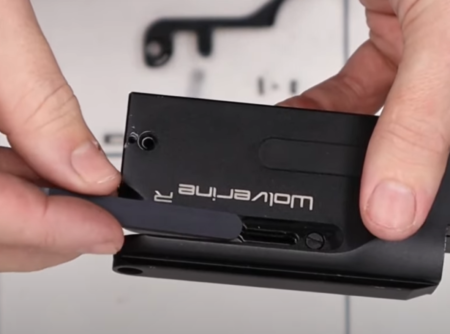
10:00 Insert the hammer into the front of the main block. Ensure the screw on the hammer is aligned with a hole on the front of the block and then push it fully in. Use a razor blade or similar to lift the edge of a sticking plate on the side of the block to reveal a slot through which you can see the hammer.
Replacing the hammer
Secure the hammer using a 2.5mm Allen screw (10:35), taking care not to over-tighten. Refit the sticker plate.
Hammer securing screw replaced
INSTALLING SAFETY AND HAMMER SPRING
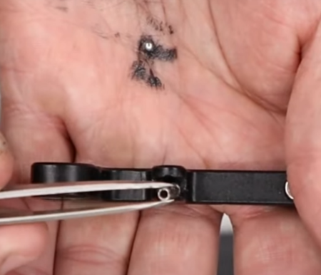
11:37 Apply a small amount of moly grease to the 5mm ball bearing. Use a pair of tweezers to insert the ball bearing into the back of the main block into a hole just behind the cocking arm retaining screw.
12:12 Apply a small amount of moly grease to the second, smaller ball bearing and small spring. Taking the safety catch housing, insert the ball bearing into the hole on the underside followed by the spring.
Replace the safety ball and spring
12:37 Take the hammer spring, aligning the front guide with the front of the rifle, and place into the back of the main block.
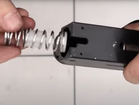
Hammer spring – note orientation
12:50 Taking care to avoid the spring or ball bearings falling out, offer the safety housing to the back of the main block and onto the hammer spring. You may need to push down the safety pin and spring to insert the safety housing (13:06).
Replace safety assembly
13:28 With light pressure to keep the safety house in place, secure with a 2mm Allen screw on the rear right side of the main block.
13:45 On the opposite side, UK spec 12 ft/lbs rifles are fitted with a small, three-pin anti-tamper screw. This screw is not fitted to export and FAC versions of the Wolverine R. To reinsert the anti-tamper screw use the 3 pin M3 A/T removal tool (small) available from Daystate part number DANTITOOLWL
INSTALLING THE TRIGGER
14:19 Attach the plastic trigger guard to the trigger housing using screws at the front and back of the trigger guard using a flat bladed screwdriver.
14:40 Place the trigger spring on top of the sear adjustment screw.
14:51 Match the trigger unit to the underside of the main block, aligning the safety unit pin with the second of two holes at the rear of the trigger unit.
15:08 Insert the four 2mm Allen screws to attach the trigger unit to the main block. Do not tighten them at this stage.
15:30 Cock the action with the side lever. Then, with the side lever open and with pressure on the trigger assembly, tighten the four retaining screws. Pull the trigger to fire the action.
Cock the hammer back before fully seating the trigger unit
REGULATOR ASSEMBLY AND INSTALLATION
16:02 Add a small amount of silicon grease to the ‘o’ rings at the top and bottom of the regulator piston.
16:10 If you removed them, ensure the Bellville washers are ordered correctly. The Bellville washers are cupped in three pairs. The first two pairs are cupped in the same direction with the third pair cupped the other way and facing towards the small end of the piston.
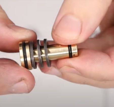
Washer sequence
16:28 Insert the piston in the regulator body, pushing it all the way home.
16:35 Drop the white seal disc it into the top of the regulator housing and make sure it lays flat.
16: 48 Add a small amount of silicon grease to the ‘o’ ring on the adjuster screw. Push it into the top of the regulator housing and tighten using a flat head screwdriver.
17:10 Moving the adjuster screw in or out will determine regulator pressure and therefore power output. Measuring the distance between the top of the adjuster screw and the regulator housing when you disassembled the regulator (see Wolverine R disassembly guide) will enable you to achieve the same or similar output when re-assembling.
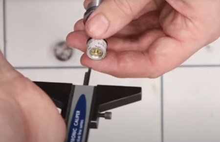
Reset regulator
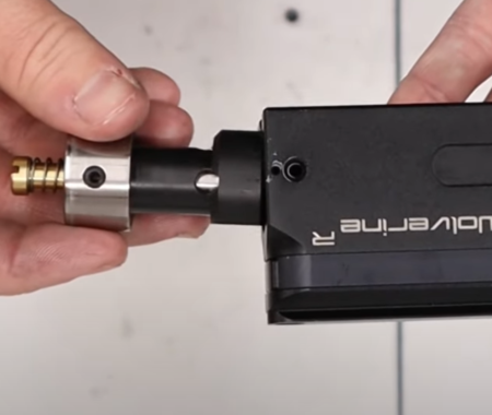
17:38 Screw the back cap on to the regulator housing, adding a light coat of silicon grease to the ‘o’ ring inside the cap. Hold the cap in a set of parrot grips and tighten the regulator with a 22mm spanner.
18:05 Apply a light cover of silicon grease to the visible o’ rings.
18:13 Screw the regulator into the front block, tightening with a set of parrot grips.
A separate regulator service video is available here
FRONT BLOCK ASSEMBLY
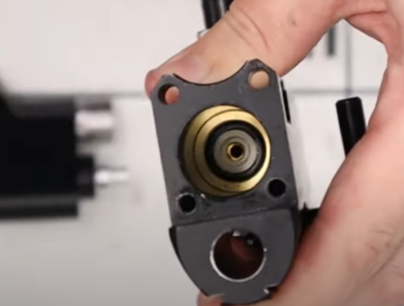
18:36 Drop the brass-coloured cup into the hole forward of the regulator.
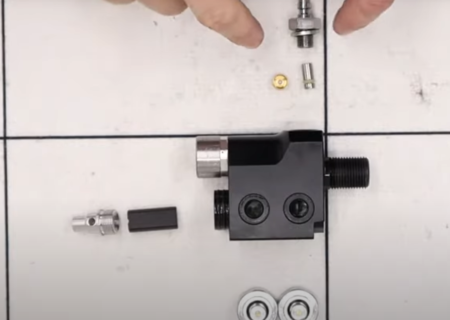
Front block assembly
Insert the one-way valve into the foster fit housing (18:47) with the ‘o’ ring uppermost and apply a light coating of silicon grease. Push the one-way valve fully home and place the doughty washer over the thread (18:55).
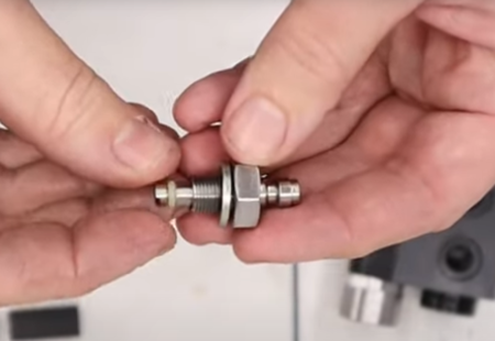
One way valve re-assembly
Screw into the bottom of the front block on top of the brass-coloured cup and tighten with a 5/8 ring spanner (19:03).
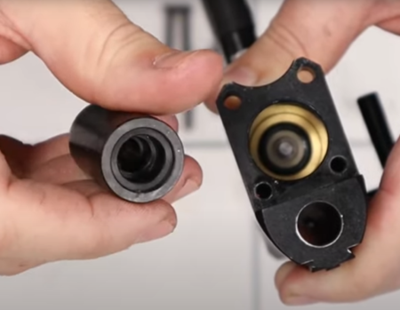
19:15 To re-install the valve spring housing, first insert the plug into the hole below the regulator. Note: that this plug may not be present on export/FAC models. Then screw in the valve spring housing, using an Allen key or similar through the holes to tighten (19:28).
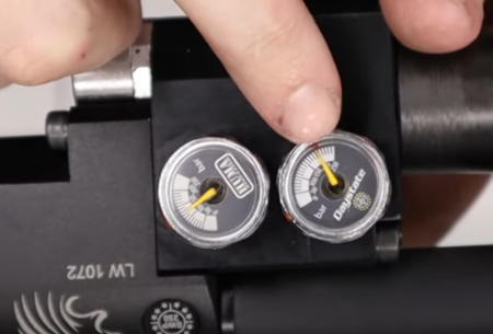
19:40 The Wolverine R is fitted with two gauges for overall air fill pressure and regulator pressure. Both are fitted with doughty washers on the thread. The air fill pressure gauge (marked ‘Daystate’) is screwed into the front hole furthest from the regulator (19:50) and tightened with a 22mm spanner. The ‘Huma’ labelled gauged (regulator pressure) is screwed into the hole next to the air fill pressure gauge, tightened once again with a 22mm spanner (20:05).
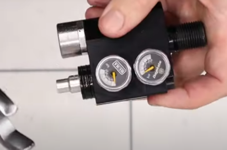
Gauge installation
FITTING THE FRONT BLOCK AND VALVE PIN/SPRING
Now you have re-assembled both the main block and front block, they need to be joined together.
On the main block:
20:22 Apply a small amount of silicon grease to the valve seat ‘o’ ring. The valve seat must be oriented properly in the block.
The valve seat must be oriented properly in the block
Drop in in and ensure the counterbored side faces up and the flat side faces down against the brass-coloured valve (20:34). Ensure it is located in the centre of the valve housing (20:44).
20:50 Take the valve pin and place it into the centre of the hole in the valve seat ensuring the ridged end is uppermost. A pair of tweezers may help. Push the valve pin down so it goes through the valve seat ‘o’ ring (20:56).
Delrin plug fitted to low powered models
21:00 Take the Delrin plug and drop it over the valve pin, ensuring the end with several counter bores is uppermost. Then drop the valve spring into the centre of the plug over the valve (21:12). Note that export/FAC rifles may not be fitted with the Delrin plug.
On the front block:
21:25 Apply a light coating of silicon grease to the two ‘o’ rings behind the valve spring housing. Align the front and main blocks together, push gently (21:30). Take the two longer screws and insert them at the top of the from block (21:42). Insert the two shorter screws below from the other side of the front block. The screws are tightened with a 4mm Allen key. However, on sub 12 ft/lbs rifles, one of the shorter screws is an anti-tamper screw, requiring a – one of which will be an anti-tamper screw and will require the use of the 3 pin M5 A/T removal tool (large)- available from Daystate part number DANTITOOLXX.
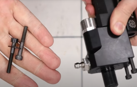
Align the two blocks together and replace screws
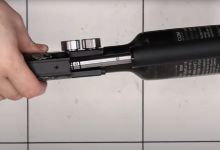
22:40 To re-attach the air bottle, first give the large ‘o’ ring a light coat of silicon grease before placing over the thread at the front of the block, then screw on the bottle by hand.
BARREL INSTALLATION AND SHROUD ASSEMBLY
23:09 Slide the rear threaded boss of the shroud over the back of the barrel, aligning dimples on the barrel with holes in the boss so you can screw in two grub screws using a 2mm Allen key (23:24).
23:37 The second boss is attached to the front end of the barrel. Slide it on an align two dimples in the barrel with holes in the boss. Secure the boss by screwing in two grub screws with a 2mm Allen key.
23:54 The shroud can then be slid over the barrel and screwed into the boss at the rear of the barrel.
24:04 The barrel is inserted into the block by aligning two dimples on top of the barrel that is not covered by the shroud with two grub screw holes on the top of the block. Tighten the grub screws with a 2.5mm Allen key.
Replace barrel in the correct orientation
PRESSURISING THE RIFLE AND SETTING POWER
24:42 Now you have re-assembled the Wolverine R you will want to check for leaks. Simply fill to a specific pressure – say 150 bar – and then leave it for a few hours before checking the gauge to see if any pressure has been lost.
Re-fill and leave overnight to check for leaks
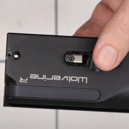
25:22 Note that an antitamper bar prevents adjustment to sub 12 ft/lbs rifles, so the following applies only to export/FAC models.
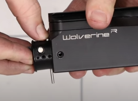
To re-set the power output you will need a 2mm Allen Key and a long 3mm Allen key. Ensure the safety catch is engaged and the rifle is safe (25:35). Insert the 3mm Allen key through the hole below the safety catch at the rear of the block to engage with the back of the hammer. Rotate the hammer so a locking screw is exposed in a slot on the underside of the block forward of the trigger.
26:11 Using the 2mm Allen key to loosen the locking screw. Once it is loose, you will be able to adjust the power. Using the 3mm Allen screw, screwing in will increase the power, and screwing out will decrease the power. Once you have made your adjustment, re-tighten the locking screw with the 2mm Allen key.
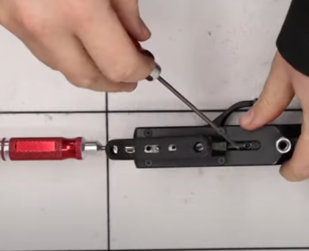
Adjusting power with the 3mm long adjuster and a short 2mm locking screw
Use a chronograph to check out levels and repeat the process to adjust accordingly.
It is important that you remove the two Allen keys before test dry firing the rifle.