THE RED WOLF
Disassembly Guide


ON THIS PAGE
- Tools you will need
- Removing the stock
- De-gassing and removing the bottle
- Removing the barrel and disassembling the shroud
- Removing the trigger and electronics assembly
- Front block removal
- Removing the pressure sensor
- Removing cocking linkage
- Removing safety and hammer assembly
- Valve core removal
- Troubleshooting
INTRODUCTION
Daystate air rifles are engineered to the highest standards, but like anything else, they require repairs and servicing work to be carried out both in and out of warranty.
The aim of this guide and the accompanying video is to provide instruction on how to re-assemble the Daystate Red Wolf.
Compressed air is dangerous. You should only use this guide if you are a qualified and experienced gunsmith used to working with compressed air. Before you carry out any work on the Daystate Red Wolf, or any PCP air rifle for that matter, you must ensure it is not cocked, not loaded and empty of air.
It is advised that you disconnect the battery and leave the rifle overnight to ensure any charge in the capacitors to discharge fully. The battery is disconnected by opening the cap at the bottom of the pistol grip (01:02). Ensure that you pull the connectors apart by holding onto the plastic components and not the wires.
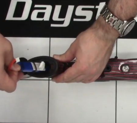
Disconnect and remove the battery
HISTORY
The Red Wolf was Introduced in 2017 with the initial rifles being a limited-edition Serie Rosso version. The red wolf shares many of the components of Pulsar, incorporated an integral display screen to the main processor board. Three lower-profile capacitors allow the electronics to be contained within a single weatherproof box. In 2020 the Red Wolf received new GCU 2.0 electronics with improved capacitors for higher power, a higher capacity 11.1 v battery and revised software. There have been two limited edition versions of the Red Wolf the 2017 serie Rosso and the 2020 Heritage LE.


TOOLS YOU WILL NEED (01:35)
- Allen keys ranging from 1.5mm to 5mm. You will also need an 8mm allen key and 0.89mm allen key
- Long nose pliers
- Soft face mallet
- Open ended 22mm spanner
- 5/8 ring spanner
- 3 pin anti-tamper removal tool DANTITOOLWL
- Tweezers
- Magnets
- Flat bladed screwdrivers 1.5mm and 3mm wide
O rings used in Red Wolf
| Red Wolf | Size | IMP or Metric | Shure | LOC | |
|---|---|---|---|---|---|
| 1 | 2 x 1.5 | M | N70 | 0.22 | |
| 2 | 18 | IMP | N70 | ||
| 1 | 006 | IMP | N70 | Striker valve seal | |
| 1 | 114 | IMP | N70 | ||
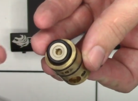
| 2 | 19.5 x 1.5 | IMP | N70 | Valve core | |
| 1 | 617 | IMP | N70 | ||
| 1 | 006 | IMP | Urethane | ||
| 1 | 111 | IMP | |||
| 1 | 7.1 x 1.6 | M | N70 | 0.30 | |
| 1 | 4 x 1.5 | M | N70 | 0.177 | |
| 1 | 5 x 1.5 | M | N70 | 0.22 | |
| 1 | 6 x 1.5 | M | N70 | 0.25 | |
| 2 | 10 x 1 | M | N70 | ||
| 2 | 12 x 1 | M | N70 |
REMOVING THE STOCK
02:18 Remove the stock bolt on the underside of the stock with an 8mm allen key. It advisable to open the battery cover in the pistol grip to ensure the wire does not get caught up when pulling the stock off.
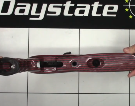
Stock removal is by a single M12 bolt – but don’t forget to remove the battery first
DE-GASSING AND REMOVING THE BOTTLE
Note: It is critically important that you de-gas the Red Wolf before undertaking any work.
02:56 Loosen the foster fitting on the underside of the action using a 5/8 ring spanner until you can hear air escaping. Leave the rifle until no more air can be heard. This should only take a minute or two. The rifle will be empty when the foster fit is loose. Any resistance will indicate air remaining.
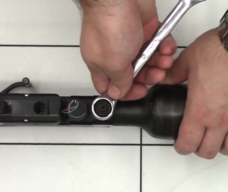
Removing the filling assembly
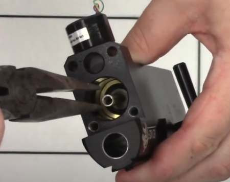
03:31 With the foster fitting fully removed, the one-way valve can be pushed out using a 1.5mm allen key.
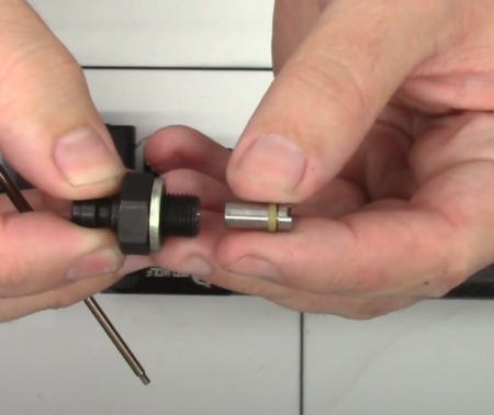
Filling fitting components note the orientation of the piston
03:54 The air bottle can be removed by unscrewing it.
04:09 Remove the ‘o’ ring on the thread to the bottle connection.
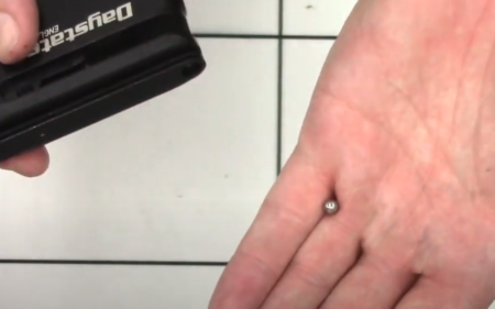
04:24 Remove the silver cup in the valve seat that was uncovered when the foster fitting was removed. This is done simply by tapping the action into your hand.
REMOVING THE BARREL AND DISASSEMBLING THE SHROUD
04:44 Use a 2.5mm allen key to loosen the two screws at the top of the block just forward of the breech. The screws do not have to be removed in order to remove the barrel. The barrel will then pull out of the block.
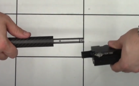
Barrel removal
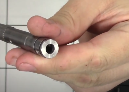
Note breech oring inside the barrel
05:02 Remove the allen screws on the underside of the shroud using a 2.5mm allen key. The carbon shroud can then be pulled off the barrel.
05:31 The carrier at the back of the barrel can be removed by loosening the two grub screws with a 2mm allen key. The carried will then slide off the barrel.
05:52 The component on the muzzle end of the barrel simply unscrews. If necessary, insert a large allen key or similar through the slot for additional leverage.
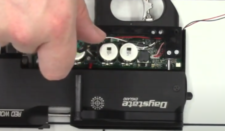
REMOVING THE TRIGGER AND ELECTRONICS ASSEMBLY
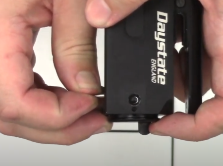
06:27 Remove the plastic cover on the side of the block using a 3mm flat bladed screwdriver to undo the three screws.
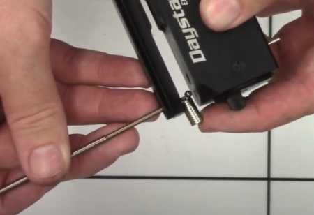
06:52 Disconnect the coil by undoing two small screws with a 3mm flat bladed screwdriver. The screws do not need to be undone all the way, just loosened.
Disconnect solenoid wires
07:14 Disconnect the three-pin connection pressure sensor. Do this carefully so as to not damage the wires.
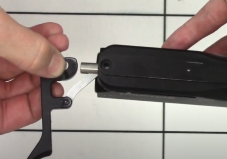
07:37 Use a 5mm allen key to loosen the allen screw in the base of the block and remove the trigger unit.
08:01 The trigger guard and trigger blade are removed by undoing the screws either side of the trigger guard with a 3mm allen key.
08:16 Use a 1.5mm allen key to push out the pin in the trigger guard at the top of the trigger blade and then pull the pin out using a pair of long nose pliers. This will remove the trigger blade assembly.
09:41 The trigger spring simply lifts out. Make sure you do not lose the small brass top hat located in the bottom of the spring.
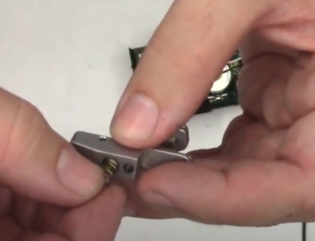
Trigger removal do not loose the spring or seating cup
09:55 The trigger switch is removed by undoing two screws with a flat bladed screwdriver and topping them out of the bottom of the trigger unit. (10:14) Then disconnect the trigger switch at the back of the unit. Take care to grip the plastic connector and do not pull on the wires themselves.
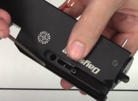
10:44 Remove the cover plate from the other side of the unit (the side with the display screen) by removing the three screws with a 3mm flat bladed screwdriver.
11:12 To separate the two halves of the board, first disconnect the safety switch, again taking care to not pull on the wires but grip the plastic connector instead.
11:34 Lift of the insulating plastic then (11:39) remove the battery wire. Note that later versions of the Red Wolf have a slightly different battery connection.
12:23 The safety switch is removed from the trigger bracket by undoing two screws with a flat bladed screwdriver. The screws are captured by two nuts so take care to not lose them.
FRONT BLOCK REMOVAL
12:53 Using a 4mm allen key, undo the four bolts at the front of the block (housing B) – two on top and two underneath. The two screws on the bottom are longer than those on the top. Note that the front block is under slight tension from a spring. With the four screws removed, ease the front block away from the main block.
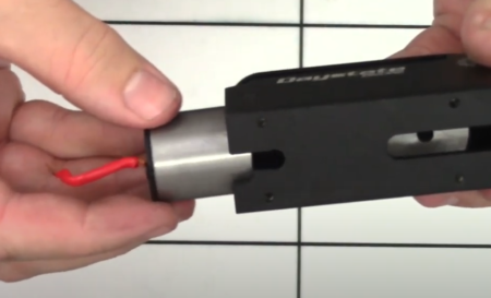
14:02 Use a set of long nose pliers, lightly grip the valve spring to pull the valve or firing pin free.
Valve removal
REMOVING THE PRESSURE SENSOR
14:38 Use a 22mm spanner to unscrew the sensor housing. Take care to not lose the small Bonded Seal (Dowty Seal) washer on the base.
REMOVING COCKING LINKAGE
15:06 Remove the cocking arm to unscrew the allen screw on the top of the block at the rear with a 2.5mm allen key. This will allow you to pull the cocking arm and pellet probe out of the back of the block. Take care to not lose the small spacer on the rear of the cocking arm.
Cocking arm removal
15:42 The cover plate that blocks off the unused cocking arm slot is removed by loosening the two screws in the block accessed through the cocking arm slot you have just revealed with a 2mm allen key. The cover plate can then be pushed out the rear of the main block.
Cover plate removal
16:21 To further disassemble the cocking arm, the spacer can be removed simply by pushing it out of the hole.
16:31 Using a 3mm screwdriver, remove the bolt that attaches the pellet probe linkage to the cocking arm. You may need a set of long nose pliers to pull the screw free.
17:00 Note that there is a spring and ball bearing in the hole in the cocking arm. To remove them you will need a pair of tweezers.
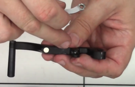
Note spring and ball inside cocking arm
17:20 The drop down handle is removed from the cocking arm by using a 2.5mm allen key to undo the allen screw.
REMOVING SAFETY AND HAMMER ASSEMBLY
17:35 To remove the ball bearing located in the large of two holes at the rear of the block above the safety catch, tilt the block and flip the safety catch. The ball bearing will then fall out.
Remove ball from rear large hole in safety catch
17:58 Before removing the anti-tamper screws on either side of the block, it is important that you remove a small spring and ball bearing located in the rear most hole above the safety switch. Failure to do this will result in the safety switch getting jammed on the spring when you remove it.
18:28 To remove the spring is to use an allen key and small magnet. (18:35) Put the allen key through the hole in the top of the block and into the hole containing the spring, then place the magnet on the side of the allen key just above the bottom hole (18:43). Pulling up the allen key should then result on the spring coming with it thanks to the magnet. (18:58) Repeat the process to remove the ball bearing.
Using a magnet to remove spring and ball from safety catch
19:27 Anti-tamper screws on either side of the block are only present on sub-12ft/lbs rifles. To remove them you will need the Daystate anti-tamper tool DANTITOOLWL. (19:44) The anti-tamper tool fits an 8mm socket.
20:12 Pull down the shaft at the bottom of the block underneath the safety catch, pulling the safety switch backwards at the same time. Take care to not lose the wave ring. Note that some models have a thin ‘o’ ring instead.
Pull down the shaft to allow the safety catch assembly to be removed
20:50 The hammer and hammer return spring will tip out of the back of the block.
21:00 Remove the Delrin hammer housing which again will tip out of the back of the block.
21:08 To remove the coil you will need to carefully bend the wire through the slot and into the block. The coil will then slide out of the back of the block. (21:31) A metal disc spacer will also come out.
Coil removal
VALVE CORE REMOVAL
21:53 Undo the two bolts located at the bottom of the breech using a 2mm allen key. The bolts hold on a plate that has a spring underneath, so take care not to lose the spring when removing the plate.
22:12 Use a set of tweezers to remove the spring and then (22:22) the magazine indexing pin underneath. (22:36) The pin can be removed from the housing by first removing the small ‘o’ ring underneath. Note that Red Wolf rifles with the later self-indexing, gate-fronted magazine do not have this component.
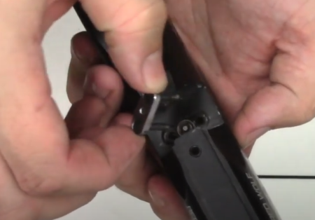
Removal of cover plate must be carried out without air in the rifle
Indexing pin components. Replaced on later rifles with a blanking pin
Later blanking pin still requires the oring
23:17 The valve core can now be pushed out of the block. Use an allen key to push on either the top or bottom hole visible through the front of the block. The valve core will come out of the back of the block (23:38).
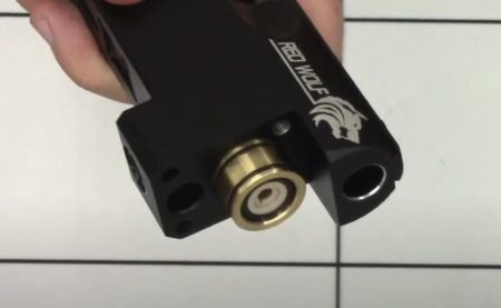
Valve core removal
23:50 The valve seat can be removed by teasing it out with an allen key.
Valve seat removal, note orientation
TROUBLE SHOOTING
26:39 The barrel has three ‘o’ rings at the breech end – two on the outside of the barrel and a breech seal inside. If one of the two exterior ‘o’ rings has been compromised, you may feel a puff of air through the front or middle of the block. Similarly, you will feel a puff of air if the breech seal is compromised. To resolve the issue, replace the ‘o’ rings.
27:32 On older models that have a magazine indexing pin. Over time it is possible for the indexing pin to become worn or broken. This can be indicated by a puff of air coming out of the top of the block once the rifle has been fired. To resolve the issue, replace the indexing pin.
28:15 The join between the main block and the front block is a common cause of air leaking. To test for an air leak, drop some soapy water onto the join and look for air bubbles. To resolve the issue, replace the two ‘o’ rings.
28:40 Air leaking through the foster fitting is likely to be cause by a failed ‘o’ ring on the one-way valve located within the foster filler housing. To resolve, replace the ‘o’ ring. Less likely is a failure in the doughty washer on the foster fitting thread.
29:22 Air escaping through the end of the barrel (you can test by putting a balloon over the end of the barrel and leaving it overnight) is likely to be caused by damage to one of the two ‘o’ rings on the valve core. Air will escape through the valve and travel through the transfer port and through the barrel. To resolve, replace the ‘o’ ring.
29:52 Air escaping through the barrel could also be caused by damage to the valve face. To resolve, replace the valve face.
30:24 Less common is an air leak from the pressure sensor as a result of a compromised dowty washer. To resolve, replace the doughty washer.
30:30 Less common is an air leak from the neck of the air bottle as a result of damage to the ‘o’ ring seal. If you suspect this to be faulty, it is vital that you de-gas the rifle before removing the air bottle and replacing the ‘o’ ring.