THE RED WOLF
Assembly Guide


ON THIS PAGE
- Tools you will need
- Installing the valve
- Hammer assembly and installation
- Installing the cocking arm and pellet probe
- Reinstalling the pressure sensor
- Reinstalling the front block
- Installing electronics and trigger
- Reinstalling the foster fitting and air bottle
- Shroud assembly and barrel installation
- Refitting the stock
INTRODUCTION
Daystate air rifles are engineered to the highest standards, but like anything else, they require repairs and servicing work to be carried out both in and out of warranty.
The aim of this guide and the accompanying video is to provide instruction on how to re-assemble the Daystate Red Wolf.
Compressed air is dangerous. You should only use this guide if you are a qualified and experienced gunsmith used to working with compressed air. Before you carry out any work on the Daystate Wolverine, or any PCP air rifle for that matter, you must ensure it is not cocked, not loaded and empty of air.
TOOLS YOU WILL NEED
- Allen keys ranging from 1.5mm to 5mm. You will also need an 8mm allen key and 0.89mm allen key
- Long nose pliers
- Soft face mallet
- Open ended 22mm spanner
- 5/8 ring spanner
- 3 pin anti-tamper removal tool DANTITOOLWL
- Tweezers
- Magnets
- Flat bladed screwdrivers 1.5mm and 3mm wide
O rings used in Red Wolf
| Red Wolf | Size | IMP or Metric | Shure | |
|---|---|---|---|---|
| 1 | 2 x 1.5 | M | N70 | 0.22 |
| 2 | 18 | IMP | N70 | |
| 1 | 006 | IMP | N70 | |
| 1 | 114 | IMP | N70 | |
| 2 | 19.5 x 1.5 | M | N70 | |
| 1 | 617 | IMP | N70 | |
| 1 | 006 | IMP | Urethane | |
| 1 | 111 | IMP | ||
| 1 | 7.1 x 1.6 | M | N70 | 0.30 |
| 1 | 4 x 1.5 | M | N70 | 0.177 |
| 1 | 4 x 1.5 | M | N70 | 0.22 |
| 1 | 6 x 1.5 | M | N70 | 0.25 |
| 2 | 10 x 1 | M | N70 | |
| 2 | 12 x 1 | M | N70 | |
| 3 | 017 | IMP | N70 | |
| 1 | 111 | IMP | Urathane |
INSTALLING VALVE CORE
0:21 The two ‘o’ rings around the valve core are 19.5 x 1.5. The ‘o’ ring in the base is BS006. The ‘o’ ring around the outside of the valve seat is a BS111.
00:53 Put a small amount of silicon grease over the ‘o’ rings.
01:00 Drop the valve core into the block, ensuring the transfer port and recessed indexing pin hole is facing the top of the block. Take care not to damage the ‘o’ rings as you push the valve core in past the edge of the block.
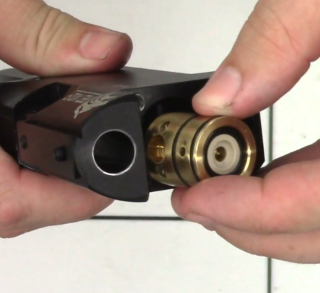
Replacing the valve core
01:20 Ensure the transfer port and recessed indexing pin hole is properly oriented by looking through the base of the breech.
01:31 Insert the magazine index ‘o’ ring (2 x 1.5) into the indexing pin hole visible through the bottom of the breech. Use a small allen key to ensure the ‘o’ ring is properly seated.
01:51 Place the silver cup over the ‘o’ ring.
01:58 Place the magazine indexing pin through the cup longest end first. note that on later rifles a blanking-dowel replaced the indexing pin assembly, but the ‘o’ ring is retained.
02:08 Drop the spring over the top of the pin.
02:13 The cover is then screwed into position over the top using a 2mm allen key to secure the two screws.
ASSEMBLING AND INSTALLING THE HAMMER
02:40 Drop the steel spacer into the rear of the block.
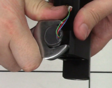
02:45 Insert the coil on top of the spacer ring ensuring the wire is aligned with the slot at the bottom of the block. Pull the wire through the long slot at the base of the block.
03:03 Take the Delrin component and place into the block with the recessed slot aligned with the slot and pull the wire through the block.
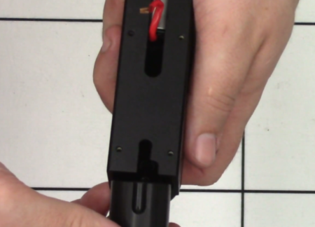
Coil assembly
03:13 Drop the hammer through the Delrin component followed by the wave ring.
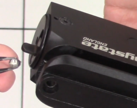
03:23 The safety catch can then be located in the back of the block. Pull the shaft down so it locks into the block.
Replacing the safety
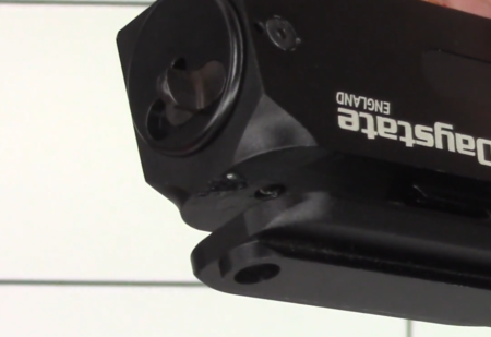
03:40 Anti tamper screws are only fitted to sub-12 ft/lbs rifles. Use the Daystate anti-tamper tool DANTITOOLWL to screw in the anti-tamper screws into the block just forward of the safety catch.
03:58 Use a cocktail stick or similar to put a light coat of lithium grease on the smaller of the two safety catch ball bearings and drop it into the rear hole at the top of the safety housing inside the block. Push it down so it is properly seated.
Replacing the safety ball and spring
04:23 Apply a small amount of lithium grease to the safety spring and place it in the same hole over the ball bearing.
04:47 Insert the largest safety catch ball bearing in the second, larger hole having first covered with a small amount of lithium grease. Put the safety catch into the safe position so the ball bearing sits flush.
Large safety ball bearing
Large safety ball in position
INSTALLING THE COCKING ARM AND PELLET PROBE
05:39 Add some moly grease inside the forward of the two holes on the cocking arm that receive the pellet probe.
05:49 Drop the spring into the hole and push it down with a cocktail stick or similar. (06:03) Drop the ball bearing down on top of the spring and then apply a coat of moly grease on top of the ball bearing.
06:15 Insert the link arm of the pellet probe and align the hole in the link arm with the hole in the cocking arm so the link articulates towards to the cocking arm.
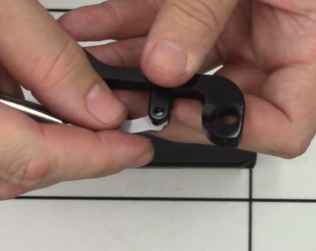
Cocking arm assembly
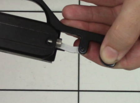
06:27 Insert the screw and tighten with a flat bladed screwdriver.
06:54 Insert the metal bush into the rear hole having first coated with lithium grease. It’s also worth coating the main shaft of the pellet probe as well as the joint between the probe and the arm linkage.
07:27 Once you have decided which side of the block you intend attaching the cocking arm you will need to first place the cover plate on the other, unused side. (07:31) Slide the cover plate in through the back of the block and tighten the two screws with a 2mm allen key.
07:51 Slide the pellet probe into the back of the block, aligning the cocking arm with the slot. (08:08) Drop the screw through the hole at the top of the block at the rear through the cocking arm/pellet probe and tighten with a 2.5mm allen key.
Replacing the pellet probe
08:26 Attach the drop down handle at the front of the cocking arm by tightening the screw with a 2.5mm allen key.
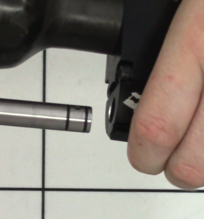
REINSTALLING THE PRESSURE SENSOR
08:37 Screw the pressure sensor into the hole at the front underside of the block and tighten with a 22mm spanner.
Pressure sensor should not be overtightened
REINSTALLING THE FRONT BLOCK
08:55 Drop the valve pin into the the block.
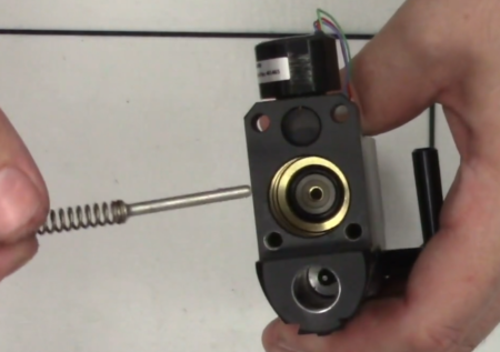
Drop the valve pin into the the block
09:04 The valve block has two 19.5 x 1.5 MBR90 ‘o’ rings. Locate the valve block over the hole into which you have just inserted the valve pin. Push it into place taking care to not damage the ‘o’ rings.
09:31 Insert and tighten the four bolts at the front of the valve block. The two shorter screws go in the top of the valve block and the longer screws go underneath from the back of the main block into the valve block. Tighten with a 4mm allen key.
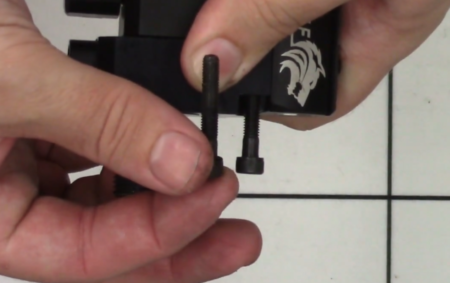
Short screws to the front of the block
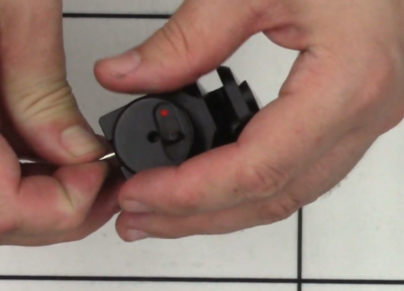
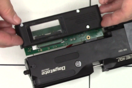
INSTALLING ELECTRONICS AND TRIGGER
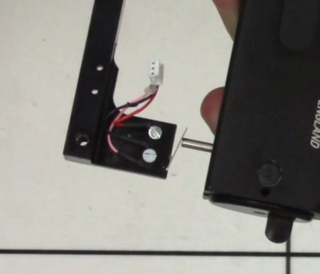
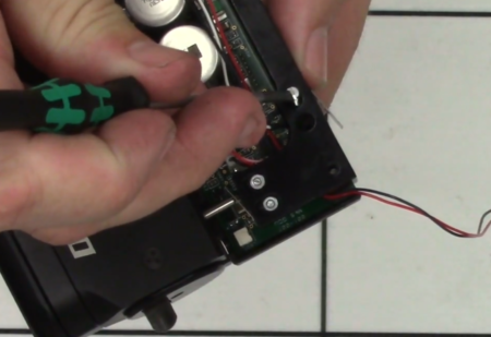
10:41 Re-attach the bracket to the base of the block. Insert the M6 screw to the forward of the two holes and together with a 5mm allen key. Do not fully tighten at this stage.
11:08 Drop the two small nuts through the slots at the back of the bracket. Put your finger over the nuts so they don’t fall out, turn the block over, flick the safety to ‘fire’ mode and then screw the safety switch into the two nuts with a flat bladed screwdriver (11:24). Do not overtighten to ensure the safety can move up and down.
12:12 Tighten the screw at the rear of the bracket with a 5mm allen key.
12:36 Adjust the safety switch to ensure it fully depresses and then tighten the screws.
Correct safety switch position
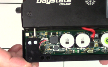
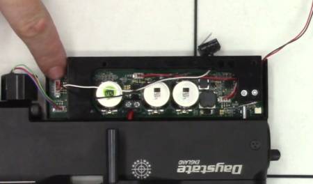
13:09 Place the insulating cover over the left side of the bracket then place the electronic board over the top, aligning the screw holes. Ensure the coil wire on the other side is not caught.
13:37 Place the cover over the electronic board. Align the screws and the screw holes and tighten with a flat headed screwdriver.
Cover plate replacement
14:16 Reconnect the safety wire to the connector block at the rear of the block.
Safety wire connection
14:30 Reconnect the pressure sensor wire to the top connector block at the front of the block.
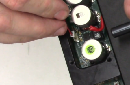
Battery wire
14:50 The battery wire is inserted through the hole at the back of the block and fed through to connect to the connector block in the middle of the electronic board.
15:20 Re-loosen the trigger bracket to re-connect the red valve core wires to the terminals then tighten with a 3mm flat bladed screwdriver. Re-tighten the trigger bracket screw.
Valve core wires
16:26 The trigger switch is re-attached by threading the wire through the trigger blade slot and connecting to the connector block at the bottom of the electronic board.
Trigger switch wires
(15:54) Place the two screws in the holes above the trigger blade slot to attach the trigger switch to the bracket.
Attaching the trigger switch
17:11 Locate the trigger blade through the top of the trigger guard aligning the holes in the blade and guard and push the pin through.
17:27 Reattach the trigger and trigger guard using the two screws at the front and back of the trigger guard. Tighten with a 3mm allen key.
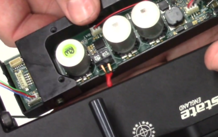
17:57 The top plate is attached over the electronic board by tightening the three screws with a flat bladed screwdriver, making sure the wires do not get caught, especially the wires connecting the pressure sensor at the front and the battery at the back.
Do not trap wires when replacing the cover plate
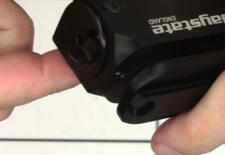
REINSTALLING THE FOSTER FITTING AND AIR BOTTLE
19:06 The foster fitting has a Dowty washer and the one-way valve has a urethane BS006 ‘o’ ring. Apply a small amount of silicon grease to the one-way valve ‘o’ ring and drop into the foster fitting with the ‘o’ ring uppermost.
19:27 Drop the cup open side up into the hole at the forward-most hole in the underside of the block. (19:35) Screw the foster fitting into the hole, tightening with a 5/8 ring spanner.
19:45 The air bottle is reattached by screwing it on the thread at the front of the block. The ‘o’ ring inside the neck of the bottle is a BS617 MBR70. Put silicon grease on the ‘o’ ring before reattaching the bottle.
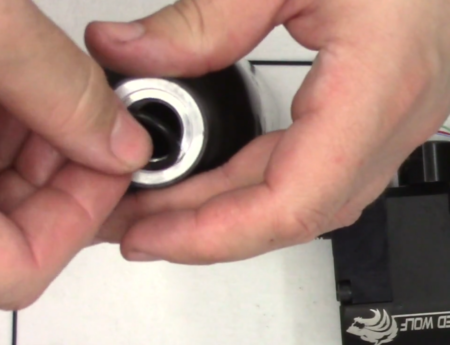
Bottle ‘o’ ring should always be replaced
SHROUD REASSEMBLY AND BARREL INSTALLATION
20:16 Reattach the shroud clamp to the rear of the barrel lining up the two grub screws with the dimples in the barrel. Tighten the grub screws with a 2.5mm allen key. Note the ‘o’ rings are BS017.
20:51 At the muzzle end of the barrel screw on the fitting. The ‘o’ ring is BS114.
21:17 The carbon shroud slides over the muzzle end of the barrel and onto the shroud clamp at the breech end, aligning the two holes on the shroud with the two holes in the clamp. (21:33) Insert the grub screws and tighten with a 2.5mm allen key. Note: The ‘o’ rings on the breech end of the barrel are 10×1 MBR70 on sub-12 ft/lbs rifles. The ‘o’ rings on FAC rated rifles are 12×1 MBR70. The breech seal ‘o’ ring is 5×1.5mm ‘o’ ring on the .22 rifle and 4×1.5 mm for the .177.
22:20 Apply a small amount of silicon grease to the two ‘o’ rings at the breech end of the barrel and insert into the breech end of the main block above the air bottle with the port hole pointing down.
Barrel orientation
22:35 Insert the two screws at the top of the block forward of the breech and tighten the two grub screws with a 2.5mm allen key. Take one of the grub screws fully out so you can ensure the holes are aligned with the two dimples in the barrel.
REFITTING THE STOCK
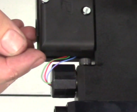
23:13 Feed the battery wire from the bottom of the block through the rearmost hole in the stock cavity through the pistol grip and drop the action into the stock. Ensure the battery wire comes out the bottom of the pistol grip.
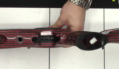
When replacing stock feed the battery wire through the grip
23:40 Place the stock bolt in the hole between the foster fitting and trigger and do up tight with a 8mm allen key.
23:56 Reattach the battery to the connector in the pistol grip. Push the battery down into the pistol grip making sure you do not pinch any wires. Close the cap on the bottom of the pistol grip.
24:21 Replace the magnetic cap over the foster fitting.
24: 31 You will likely notice a low-pressure error notice on the display screen. This is due to the fact that you de-gassed the rifle prior to disassembly. Refilling the rifle to the correct pressure will remove the warning.