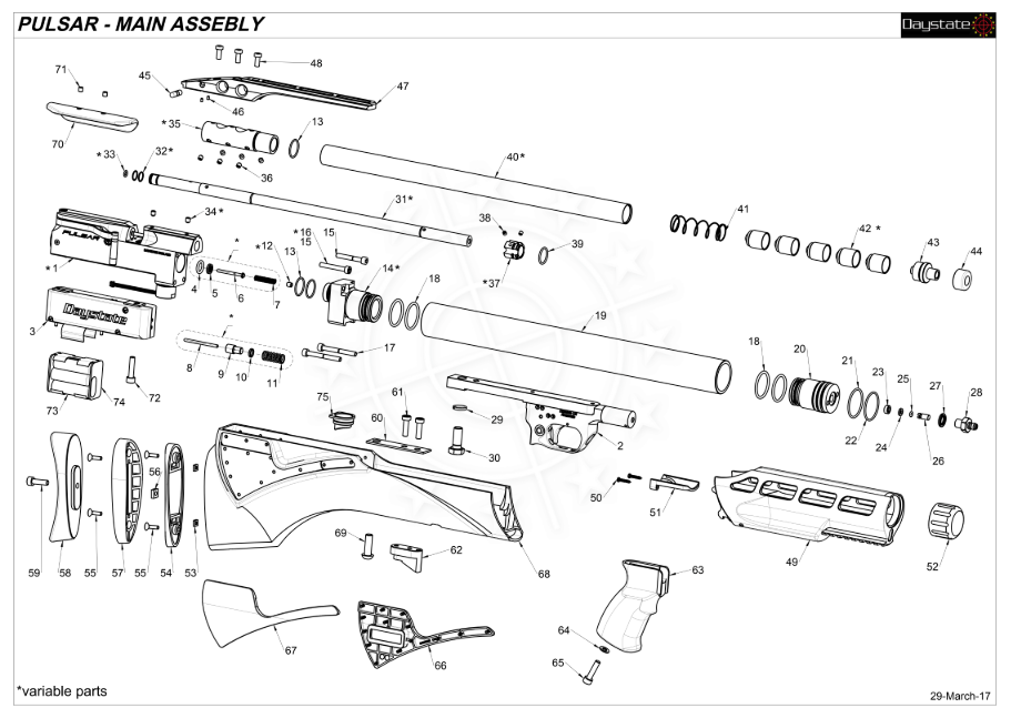
THE PULSAR
Assembly Guide
ON THIS PAGE
- Tools you will need
- Rebuilding the trigger assembly
- Rebuilding the main circuit board assembly
- Installing the valve core and indexing system
- Installing hammer assembly
- Installing the cocking arm and pellet probe
- Installing the front block and valve
- Installing the main circuit board and pressure sensor
- Installing the trigger assembly
- Installing the cylinder assembly
- Installing the barrel and shroud
- Powering up the rifle and installing the stock
INTRODUCTION
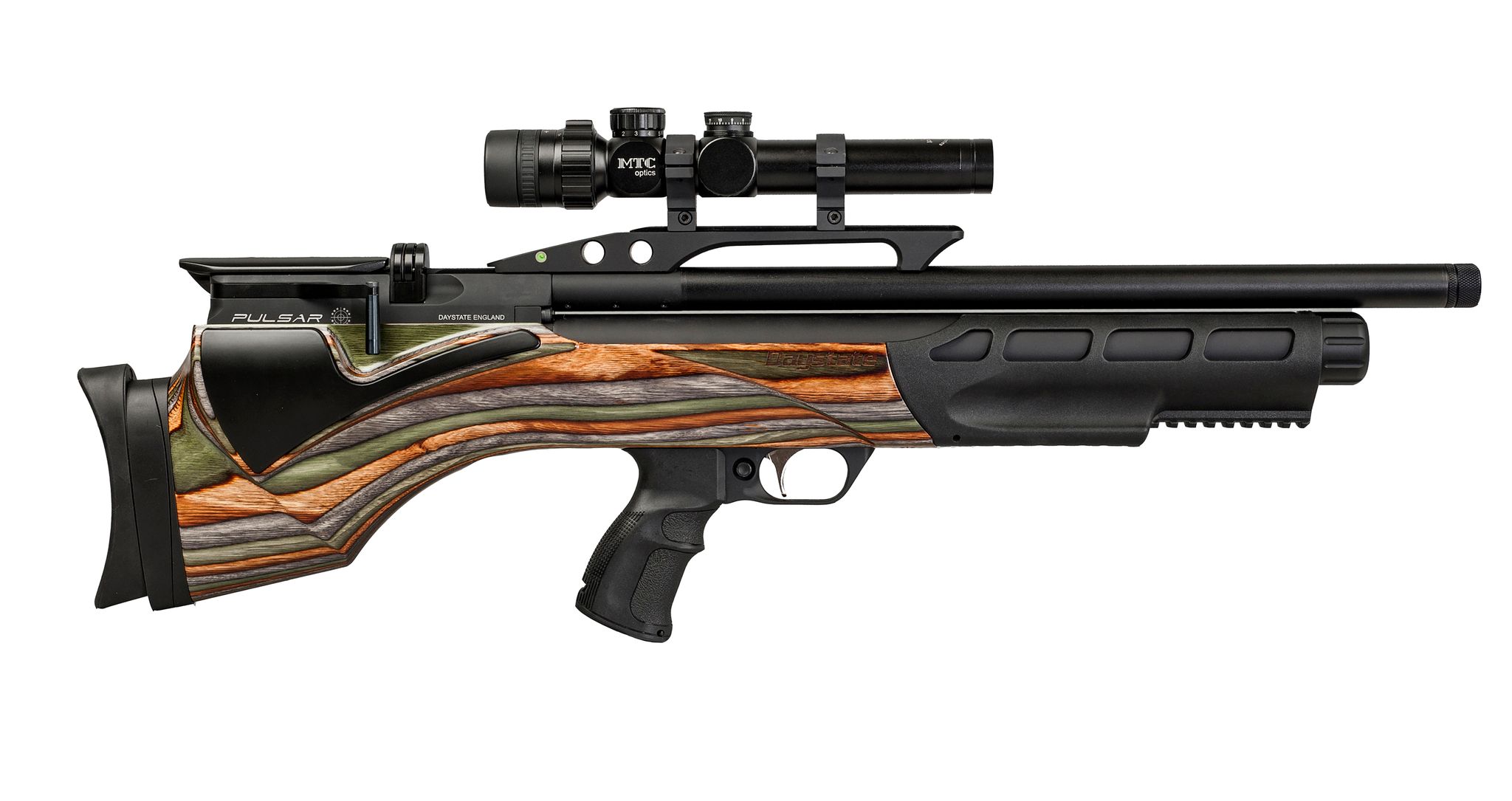 The Daystate Pulsar and Red Wolf share common components to the earlier Pulsar. Utilising a new Electronic board design called a gun control unit (GCU), the Pulsar incorporating some novel ideas such as a built-in laser and a bolt-open safety, which was carried across to the Red Wolf model when it was introduced 2 years later.
Daystate air rifles are engineered to the highest standards, but like anything else, they require repairs and servicing work to be carried out both in and out of warranty.
The aim of this guide and the accompanying video is to help you undertake work on the Daystate Pulsar to address common faults.
Compressed air is dangerous. You should only use this guide if you are a qualified and experienced gunsmith used to working with compressed air. Before you carry out any work on the Daystate Pulsar, or any PCP air rifle for that matter, you must ensure it is not cocked, not loaded and empty of air.
TOOLS YOU WILL NEED
- Allen keys: 1.5mm, 2mm, 2.5mm, 3mm, 4mm and 5mm
- Spanners: 16mm, 17mm, adjustable
- 3 pin tool
- Tweezers
- O ring pick
- 3mm wide flat bladed screwdriver
- Degassing tool
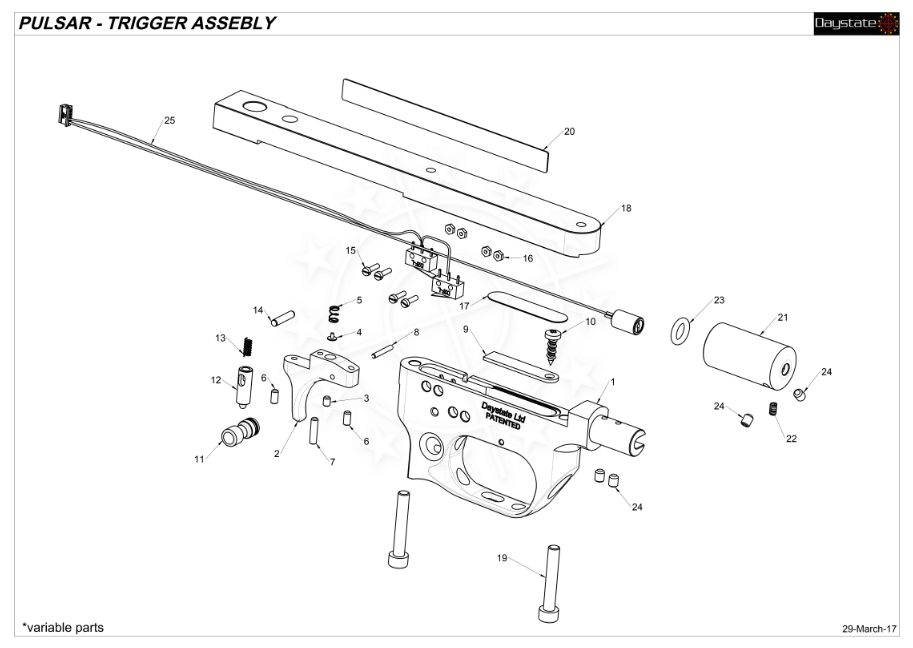
REBUILDING THE TRIGGER ASSEMBLY
01:16 Install the safety bar into the hole to the rear of the trigger guard with the red indicator positioned to the left side of the rifle.
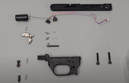
01.23 Trigger group assembly
01:23 Drop the sleeve into the forwardmost hole in the top of the trigger unit on top of the safety, aligning the hole in the side of the sleeve with a small hole in the side of the trigger unit above the safety (01:33).
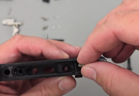
01.37 Drop the spring through the sleeve
01:37 Drop the spring through the sleeve. A pair of tweezers may help.
01:50 Install the pin through the hole above the safety on the left side of the trigger unit. You will need to depress the spring using a punch or similar. (02:06) Puch the spring down whilst also pushing the pin in so the spring is captured underneath the pin. The safety catch should now move on and off as normal.
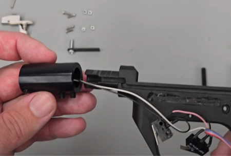
02.31 Laser assembly alignment
02:31 Take the laser assembly and locate on the front of the trigger housing, aligning the wires with the cut out on the side. Push the laser assembly into place, taking care to not pinch the wires.
02:50 Tighten the two grub screws in the bottom of the laser assembly using a 2mm allen key.
03:02 Ensure the switches are located in the correct positions at the back of the trigger assembly.
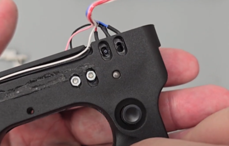
03.07 Trigger switch alignment
03:07 Secure the trigger switch, the forwardmost of the two switches, with the small screws and nuts, tightening with a flat bladed screwdriver. (03:46) Ensure the switch is supported by the trigger housing.
04:01 Insert the safety switch, tightening with the small screws and buts. Tighten with a small flat bladed screwdriver.
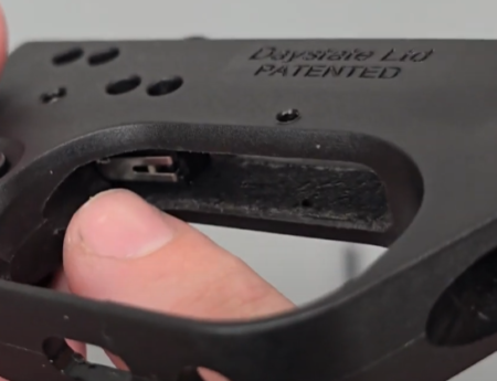
04.43 Check the trigger switch clicks before proceeding
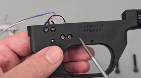
04.48 Trigger switch adjustment
04:43 Loosen slightly the switches so they move, enabling you adjust their position until you can hear the trigger switch click slightly to indicate it is in the right place (05:03). The safety switch should click with the safety catch is in the fire position (05:44), but not click when in safe (06:01).
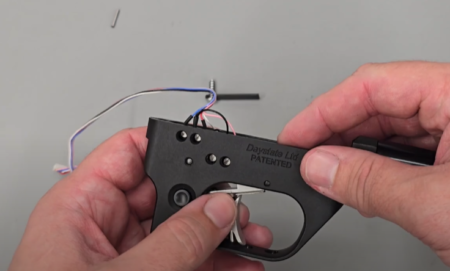
06.20 The trigger is dropped in from the top
06:20 Drop the trigger blade into the top of the trigger assembly and align the hole in the trigger blade with the small hole just above the trigger guard. Secure with the pin.
06:51 Locate the spring plate on top of the trigger blade from the top of the trigger housing with the screw forwardmost. Secure using a crosshead screwdriver.
07:15 Secure the wires to the side of the trigger assembly using a strip of electrical tape.
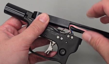
07.29 Trigger plate and wire position
07:29 The trigger assembly can now to attached to the trigger plate, taking care to not pinch any wires.
07:43 Install the two allen bolts either side of the trigger guard. Tighten with a 4mm allen key. Ensure the wires are not pinched before fully tightening.
08:06 Push the remainder of the wires into the groove and secure to the trigger assembly with a piece of electrical tape.
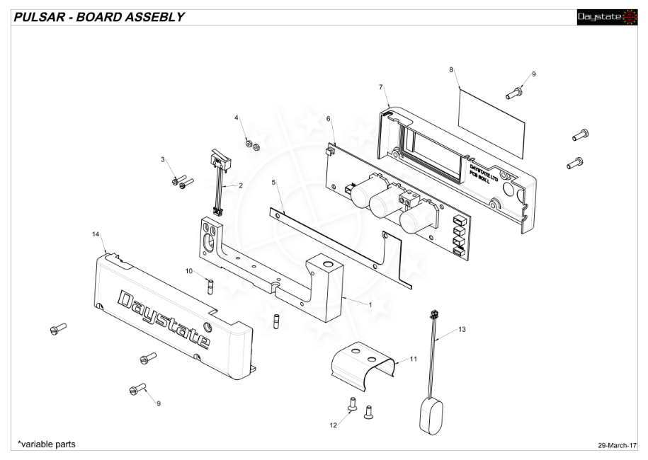
REBUILDING THE MAIN CIRCUIT BOARD ASSEMBLY
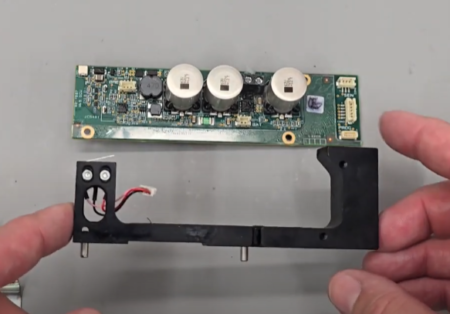
08.37 Circuit board assembly
08:37 Place the clear insulating cover on top of the circuit board, lining up the holes with the holes in the circuit board.
08:49 Drop the trigger plate on top of the circuit board and insulating cover.
09:02 Drop the circuit board onto the screen cover. Turn the sub assembly over (09:13) and secure with the three screws, tightening with a flat bladed screwdriver.
09:44 Reconnect the cocking indicator at the rear of the circuit board.
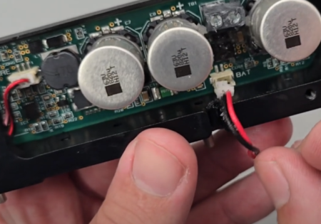
09.52 Reconnect battery and trigger plugs to board
09:52 Reconnect the battery cable, ensuring the small cut out on the cable block is aligned with the cut out in the circuit board block (10:00).
10:19 Reinstall the battery holder on the bottom of the assembly, securing with two screws and tightened with a 2mm allen key.
INSTALLING THE VALVE CORE AND INDEXING SYSTEM
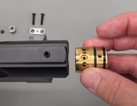
10.45 Insert the core-valve with the correct orientation
10:45 Add a small amount of silicon grease to the two large o rings on the core-valve as well as the smaller o ring on the back.
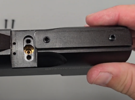
11.07 Core-valve in position – you can see the space for the o-ring
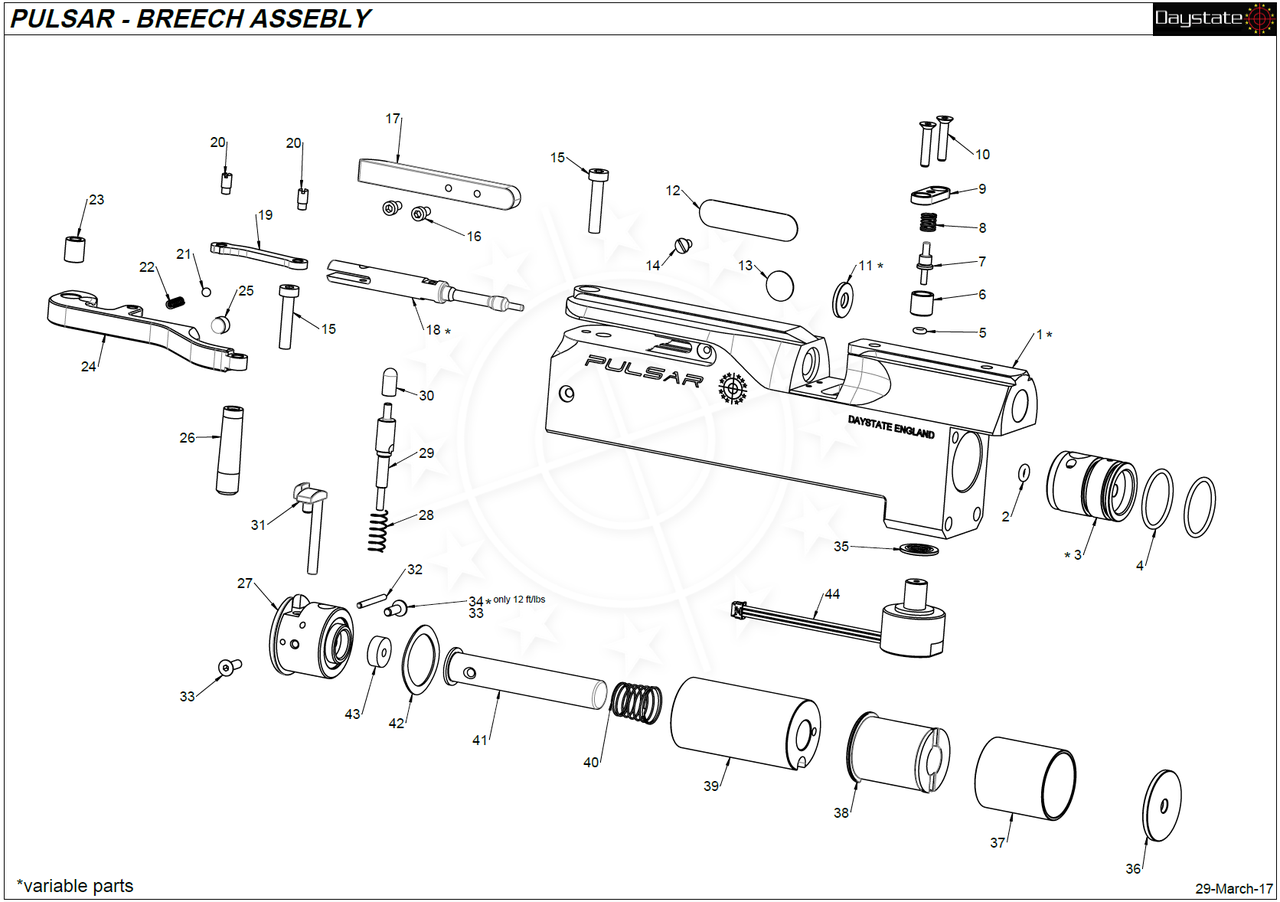
11:07 Align the transfer port on the core-valve and the hole behind it with the two holes in the bottom of the breech/magazine slot. Insert the core-valve into the bottom hole at the back of the block and push it through so the holes align (11:26).
11:31 Drop the small o ring into the hole at the bottom of the breech/magazine slot on top of the valve and ensure it is seated in the counter-bore.
11:53 Dropped the small cup on top of the o ring.
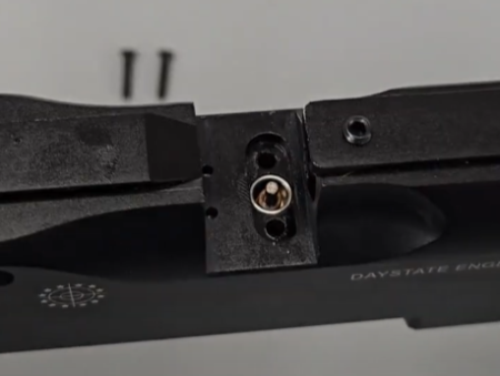
12.29 Cup and indexing pin in position
12:29 Insert the plunger, with the shorter stepped section facing up, into the cup.
12:46 Place the spring over the plunger and then place the plate (12:55) and secure with two M3 screws, tightening with a 2mm allen key.
INSTALLING HAMMER ASSEMBLY
13:55 Take the spacer washer and drop into the large hole at the end of the action.
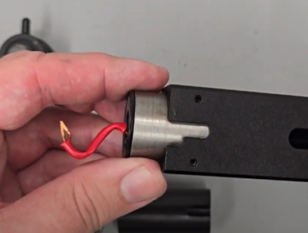
14.05 Inserting the coil
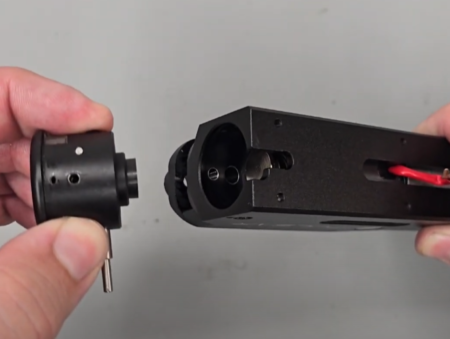
14.05 Replace the end cap, note it is necessary to pull down the plunger
14:05 Drop the coil into the same hole on top of the spacer washer with the wire pointing out of the back of the block and oriented towards the slot in the bottom of the block.
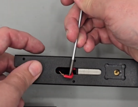
14.15 Moving the coil wire to the correct position
14:15 Hook the coil wire through the slot in bottom of the block.
14:30 Take the plastic hammer housing and place into the large hole at the back of the block with the end with a slot going first. Orient the slot in the hammer housing with the slot in the bottom of the block. Lay the coil wire into the slot on the hammer housing.
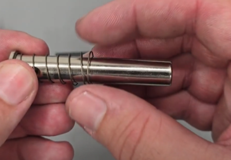
14.42 This is the correct orientation for the hammer spring
14:42 Place the hammer return spring over the hammer with the narrow end of the spring facing the back of the hammer. Drop into the back of the block.
14:59 Place the wave ring on top of the hammer.
15:04 Install the end cap, ensuring the plunger is depressed to get it to seat properly.
15:30 Secure the end cap by inserting the two screws (anti-tamper on sub 12 ft/lbs rifles).
INSTALLING THE COCKING ARM AND PELLET PROBE
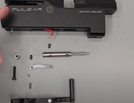
16.57 Cocking arm assembly components16:57 Apply a small amount of moly grease to the groove at the rear of the cocking arm. If you do not have moly grease, you can use lithium grease.
17:12 Insert the small spring into the hole in the link receiver in the middle of the cocking arm. Add the small ball bearing on top of the spring (17:24).
17:37 Insert the silver cocking link into the link receiver and secure with the grub screw tightening with a flat bladed screwdriver.
18:26 Apply a light amount of moly grease to the inside of the slot at the back.
18:50 Add a small amount of blue Loctite to the hole at the back of the pellet probe.
19:13 Align the hole in the cocking link with the hole in the rear of the pellet probe and secure with the grub screw, tightening with a flat bladed screwdriver.
19:36 Put a small amount of moly grease onto the body of the pellet probe. You can also put a small amount of moly grease around the hole at the rear of the main cocking arm.
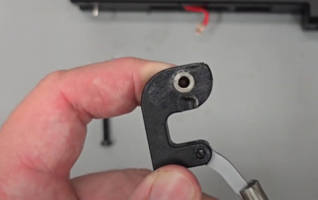
20.04 Cocking arm bush should be lubricated before assembly
20:04 Insert the cocking arm bush into the hole at the rear of the main cocking arm.
20:18 Push the assembled cocking arm into the rear of the main block. (20:20) It may be necessary to pull down on the cable on the underside of the rear of the main block to push the cocking arm into place.
20:32 Use a 2.5mm allen key and secure the screw at the back of the block to secure the cocking arm.
INSTALLING THE FRONT BLOCK AND VALVE
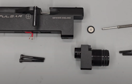
20.59 Front valve block components
20:59 Apply a small amount of silicon grease to the outside o ring on the valve seat.
21:11 Drop the valve seat into the rear of the block with the counterbored side facing uppermost.
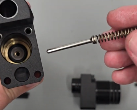
21.36 Valve and seat correctly positioned
21:36 Insert the valve pin stem first through the hole in the valve seat.
21:45 Take the front housing and a small amount of silicon grease to the two o rings on the smaller, non-threaded end.
21:56 Push the front housing into the bottom hole at the front of the block. (22:02) Secure with two long allen screws in the bottom of the main block, and two shorter allen screws to the top of the front housing (22:14). Secure all four with a 4mm allen key.
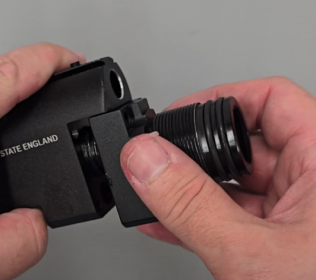
23.14 Front block assembly
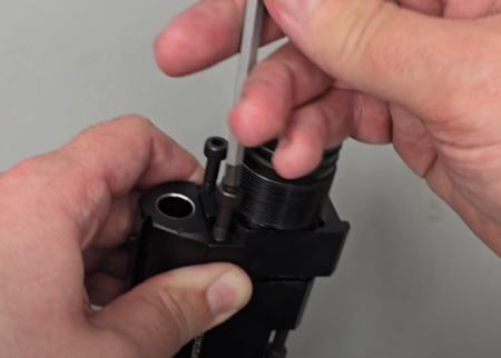
23.14 Screw in position using the 4 screws
23:14 Add a small amount of silicon grease to the o rings at the front of the top housing.
INSTALLING THE MAIN CIRCUIT BOARD AND PRESSURE SENSOR
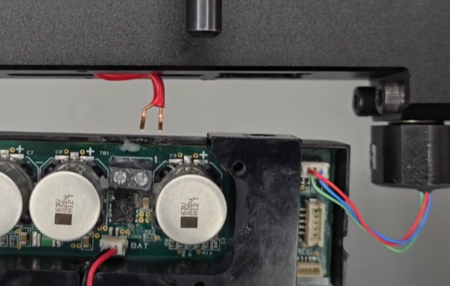
25.36 Aligning and attaching the coil
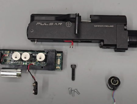
25.36 Trigger assembly
23:36 Screw the pressure sensor into the second hole back from the front underside end of the block, tightening with an adjustable spanner.
23:52 Attach the pressure sensor wire to the top right-hand corner of the circuit board.
24:12 Insert the two coil wires int the two terminals at the top of the circuit board, tightening with a small flat head or cross head screwdriver.
24:53 The board is secured to the main block by locating the trigger housing into the cut out in the main block. (25:03) Drop the large screw through the bottom of the trigger housing into the main block and securing with a 5mm allen key.
INSTALLING THE TRIGGER ASSEMBLY
25:36 Connect the wire block on the rear of the trigger assembly to the connector at the front of the main circuit board.
25:55 Attach the rear of the trigger assembly to the slot on the bottom of the main block and securing with the large bolt in the hole forward of the pressure sensor. Tighten with a 17mm spanner.
26:51 Add a small amount of dielectric grease to each of the electrical connections to prevent corrosion.
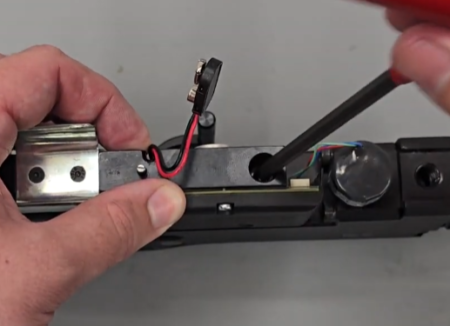
27.07 Attaching the trigger assembly
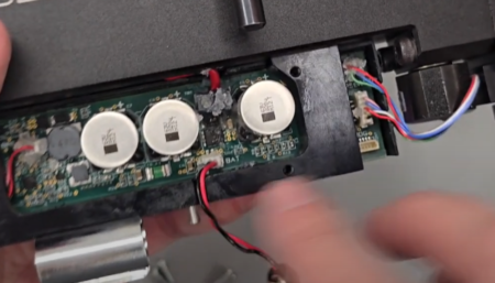
27.07 Ensure the cables are in their slots before replacing cover
27:07 Put the plastic circuit board cover onto the circuit board. Ensure the wires sit in their respective cut outs (27:18). Secure the cover with the three screws, tightening with a small flat bladed screwdriver.
INSTALLNG THE CYLINDER ASSEMBLY
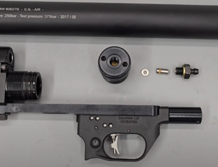
28.29 Cylinder assembly, note the date on the cylinder should be within 10 years of issue
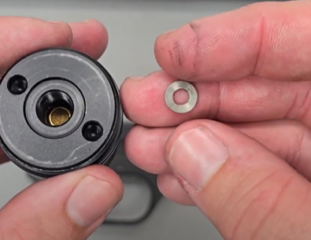
28.29 This washer sits on top of the filter
28:29 Drop the washer into the fill valve housing on top of the brass filter.
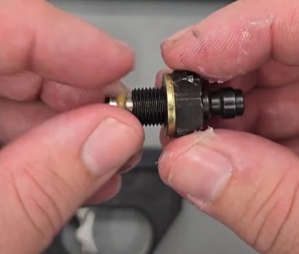
28.36 Inserting the one way valve
28:36 Add a small amount of silicon grease to the o ring on the one-way valve and insert into the foster fitting (28:46) with the shorter end uppermost.
28:56 Screw the foster fitting into the fill valve housing on top of the filter. Tighten with a 16mm spanner.
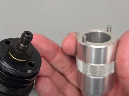
29.13 A two pin tool should be used to retighten the end plug
29:13 Apply a small amount of silicon grease to the two o rings on the front of the fill valve housing and then screw into the front of the cylinder. (29:27) Tighten using a set of snap ring pliers.
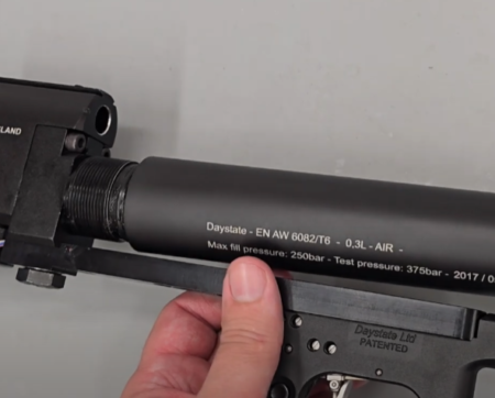
29.38 Replacing the cylinder
29:38 Screw the back of the cylinder to the front of the main block.
INSTALLING THE BARREL AND SHROUD
30:04 Slide the shroud front support over the front of the barrel, aligning the two grub screws with the dimples in the barrel.
30:19 Slide the rea shroud support to the back of the barrel. Ensure the three holes in the support are approximately in line with the two dimples in the barrel (30:33)
30:44 Apply a small amount of silicon grease to the two o rings at the back of the barrel.
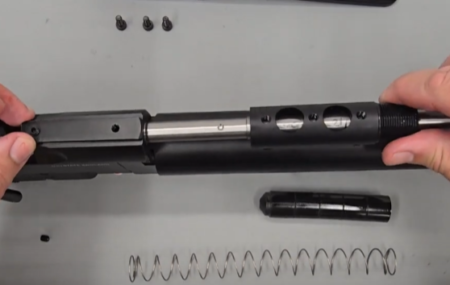
31.00 Replacing the barrel
31:00 Insert the barrel into the block ensuring the two dimples in the barrel align with the two holes in the top of the block. Secure with the grub screws and tighten with a 2.5mm allen key.
31:30 Loosen the grub screw you tighten earlier to hold the rear shroud carrier approximately in place so you can properly align the carrier with the dovetail at the top of the block and then position the scope rail (31:42) aligning the three holes in the rear shroud carrier with the three holes in the scope rail. Tighten with the three screws.
32:10 Push the scope rail hard against the block to align the two holes at the back of the scope rail and top of the block. With this done, you can tighten the grub screws in the rear shroud carrier using a 2.5mm allen key.
32:53 Insert the baffles into the barrel with the sloped end of the cones facing backwards away from the muzzle.
33:01 Place the spring on top of the baffles and then (33:03) place the shroud over the barrel and screw into place.
POWERING UP THE RIFLE AND INSTALLING THE STOCK
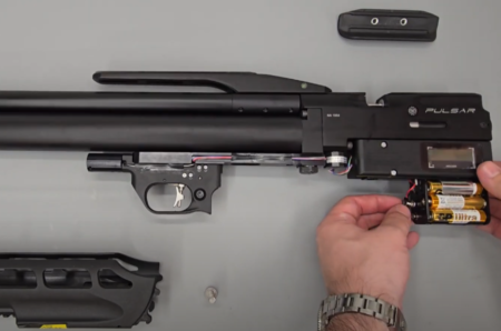
33.20 Reattaching the battery pack33:20 Reconnect the batteries in the battery pack and push into the housing. (33:25) Reconnect the batteries to the battery wire.
35:36 Slide the cheek piece onto the dovetail at the back of the rifle and secure by tightening the two grub screws using a 2.5mm allen key.
35:56 The plastic forend cover slides onto the cylinder from the front ensuring the plastic spacer is in place (36:06).
36:19 Screw the foster fit cover in place to the end of the cylinder.
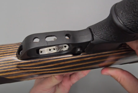
36.36 Before attaching the stock ensure the safety is in ‘safe’
36:34 Turn the action upside down, ensure the safety catch is on ‘safe’ and open the side lever. Ensure the plastic forend cover is centrally aligned and then drop the stock in place on top. (36:56) Insert the stock bolt in the hole behind the pistol grip and tighten using a 5mm allen key.
