THE HUNTSMAN REVERE
Disassembly Guide

ON THIS PAGE
- Tools you will need
- Removing the stock and de-gassing
- Barrel band removal and shroud disassembly
- Separating the top and bottom blocks
- Removing the barrel
- Removing the cocking arm and pellet probe
- Removing the air cylinder
- Removing the regulator
- Removing the fill valve assembly
- Disassembling the regulator
- Top block disassembly
- Removing and disassembling the hammer assembly
- Safety Disassembly
- Valve Assembly
INTRODUCTION
Daystate air rifles are engineered to the highest standards, but like anything else, they require repairs and servicing work to be carried out both in and out of warranty.
The aim of this guide and the accompanying video is to help you undertake work on the Daystate Huntsman Revere to address common faults.
Compressed air is dangerous. You should only use this guide if you are a qualified and experienced gunsmith used to working with compressed air. Before you carry out any work on the Daystate Wolverine, or any PCP air rifle for that matter, you must ensure it is not cocked, not loaded and empty of air.
TOOLS YOU WILL NEED (00:24)
- Allen keys: 1.5mm, 2mm, 2.5mm. 3mm. 4mm, 5mm. 1/16, 3/32
- Snap ring pliers
- Long nose pliers
- Open ended 22mm spanner
- 11mm ring spanner
- ¼ open ended spanner
- Triangle anti-tamper removal tool
- Tweezers
- Magnet
- Flat bladed screwdrivers 1.5mm. 3mm, 6mm and 13mm wide
- 2mm and 7mm punch
Before starting any work it is advised that you make a note of the regulator pressure (1:12) as you will want to ensure the regulator is re-set to the same level when re-assembling the rifle.
O rings used in Huntsman Revere
| Huntsman Regal/Revere | Size | IMP or Metric | Shure | LOC | |
|---|---|---|---|---|---|
| 1 | 003 | IMP | N70 | Bolt | .177 |
| 1 | 004 | IMP | N70 | Bolt | .22 |
| 1 | 005 | IMP | N70 | Bolt | .25 |
| 1 | 111 | IMP | Urethane | ||
| 1 | 020 | IMP | N70 | ||
| 1 | 021 | IMP | N70 | ||
| 2 | 118 | IMP | N70 | Regal | |
| 1 | 006 | IMP | Urethane | ||
| 1 | 19 x 2 | M | N70 | ||
| 1 | 008 | IMP | N70 | ||
| 1 | 014 | IMP | N70 | ||
| 1 | 010 | IMP | N70 | Regal | |
| 1 | 006 | IMP | N70 | ||
| 1 | 810 | IMP | N70 | Regal | |
| 2 | 21 x 2 | M | N70 | ||
| 1 | 22 x 2.5 | M | N70 |
REMOVING THE STOCK AND DE-GASSING
Removing the stock will make it easier to work on the rifle (and prevent any damage to it). You will need to de-gas the rifle to work on it safely.
1:28 The stock is removed by undoing an Allen bolt on the underside of the stock using a 5mm Allen key.
Remove the stock before starting any work
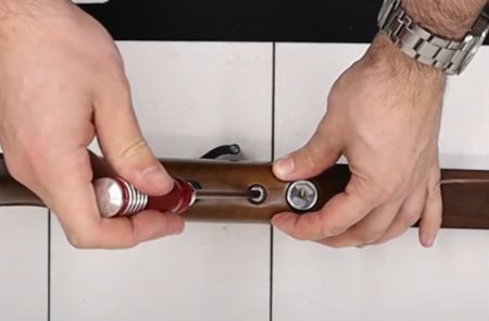
1:48 Use a 22mm spanner to crack the regulator pressure gauge loose. You will only need half a turn or so to hear the air start to escape. Leave the rifle for a few seconds until you can no longer hear any air.
Remove the air from the rifle
2:11 Check both the regulator and fill pressure gauges to check they are reading empty.
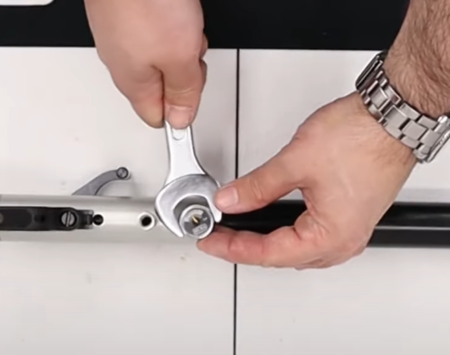
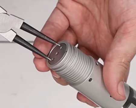
2:26 Fully remove the regulator gauge by unscrewing it.
2:29 The regulator gauge can be disassembled further. The dowty washer can be removed and by placing the connecting section in a vice lined with soft material to prevent damage, the gauge can be unscrewed.
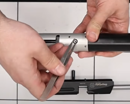
BARREL BAND REMOVAL AND SHROUD DISASSEMBLY
3:00 Remove the end cap for the fill pressure gauge by pulling it off.
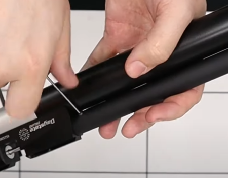
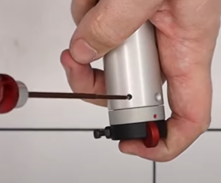
3:16 Use 1.5mm allen key, remove three grub screws that hold the barrel band and slide it off the end of the cylinder.
Remove the front barrel support
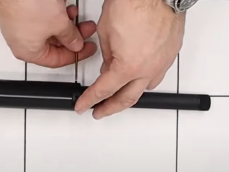
3:40 Remove the shroud by undoing the two grub screws at the base of the shroud using a 1/16 allen key.
Shroud removal
4:06 The shroud can be further disassembled by unscrewing the silencer thread protector and by using a wide flat head screwdriver to remove the silencer end cap (4:13). An ‘o’ ring will also be released (4:26). Use a pair of long nose pliers to pull out the inner end cap (4:32).
4:45 An aluminium section at the other end of the shroud is bonded in and will need heat in order to be removed if required.
SEPARATING THE TOP AND BOTTOM BLOCKS
5:06 Remove six securing screws from the top using a 2.5mm allen key.
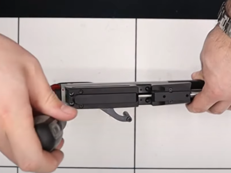
Remove the six screws securing the breechblock
5:20 Use a flat blade screwdriver to remove two slotted bolts in the middle of the block.
5:32 Use the Daystate anti-tamper tool DANTITOOLXX to remove the two triangle headed bolts located at the back of the block.
5:43 Lift the top block away from the bottom block. Take care not to lose any small components. These include a small ‘o’ ring located in a hole at the top of the bottom block (5:53), a brass transfer port (6:00) and another ‘o’ ring in the top block (06:03). You will also want to fully remove the bolts from the top section and put them somewhere safe (6:06).
Take care to remove small components
6:15 Use a pair of tweezers to remove the brass section on the underside of the top block as well as the small ‘o’ ring underneath.
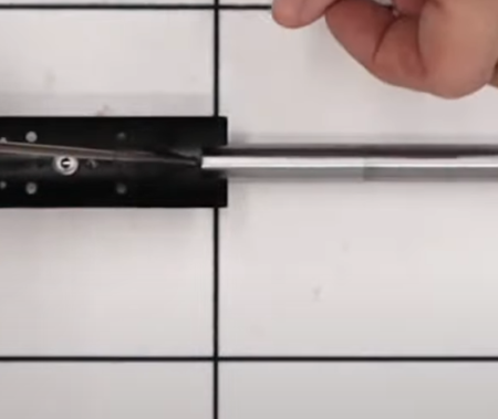
REMOVING OF THE BARREL
6:36 Remove the four retaining grub screws – two from the top of the top block and two from the underside – using a 2mm allen key. Note that the two grub screws that go in the underside of the block are shorter than those that go in the top (7:00).
Barrel is retained with 4 screws
7:10 The barrel will now simply pull free of the block.
7:20 Note that the rifle does not have an ‘o’ ring in the transfer port on the barrel as it is located on the pellet probe within the block itself.
REMOVING THE COCKING ARM AND PELLET PROBE
7:33 Turn the block upside down and remove the cocking pin using a 3/32 allen key.
7:44 Remove the cap at the rear of the block by using a 2mm allen key to remove the bolt at the back of the block (7:47). The cap will then fall out of the back of the block.
8:01 Remove the cocking side arm using a 2.5mm allen key to remove the bolt attaching the drop-down handle (8:04). Then remove the cover (8:12) using a 2.5mm allen key to undo the bolt on top of the block. Tipping the block will then allow the cover on the side of the block to be removed (8:21).
8:25 Access the inner part of the block through the cover you have just removed to undo the bolt using a 2.5mm allen key to release the cocking arm from the pellet probe (8:30). Undo the bolt on top of the block using a 2.5mm allen key to remove the cocking arm (8:43). Take care not to lose the small bush (8:52).
Cocking linkage removal
8:57 The pellet probe will now slide out of the back of the block.
REMOVING THE AIR CYLINDER
Note: it is critically important to have ensured all air has been bled from the rifle.
9:16 The air cylinder simply unscrews from the valve housing.
Removing the firing valve retainer
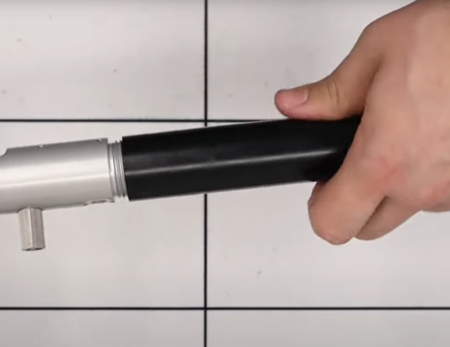
Unscrew air cylinder
A separate regulator strip and assembly video for the Huntsman Regulator is available here
REMOVING THE FILL VALVE ASSEMBLY
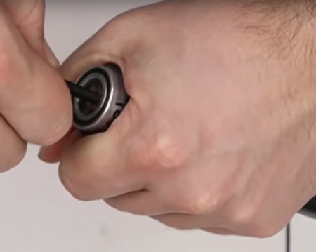
9:54 Place a 7mm punch or similar through the fill port to enable you to unscrew the assembly from the air cylinder.
10:09 Remove the one-way valve at the back of the assembly by first removing the brass-coloured filter and a spacer washer with a flat-bladed screwdriver (10:14) to expose the one-way valve.
10:29 Remove the one-way valve by applying some air pressure. Insert the fill probe used to fill the rifle with air into the fill port and connect to a dive bottle (10:36). Place gauge side up on a sturdy surface (10:52) AND NOT ON YOUR HAND.
11:02 VERY CAREFULLY open the valve on your dive bottle briefly to apply air pressure. Note that low pressure will suffice. This will eject the one-way valve (11:08).
11:16 The gauge can be removed by inserting the 7mm punch into the fill port and using a 22mm open ended spanner to release the gauge from the front of the assembly.
DISASSEMBLING THE REGULATOR
11:40 Use a set of callipers to measure the distance from the top of the adjuster screw to top of the regulator body. This will allow you to reset the regulator pressure to its original level when re-assembling the regulator.
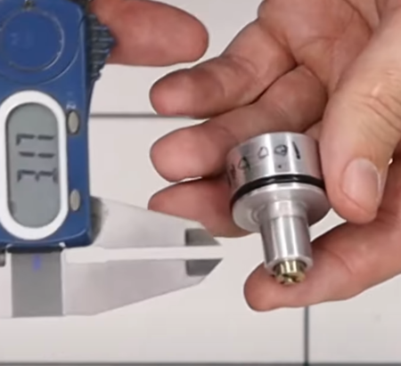
Record regulator setting before any work
12:20 Use a flat headed screwdriver to remove the adjuster screw completely. Take care to not damage the ‘o’ ring at the base of the adjuster screw (12:34).
12:40 Remove the snap ring in the bottom of the regulator using a pair of snap ring pliers.
12:48 Screw an M5 bolt into the piston in the base of the regulator and ease it out. Take care to not lose the small white sealing disc in the regulator body, nor the Belleville washers on the piston. There are six washers cupped in alternating pairs (13:11).
13:18 Gently push out the white sealing disc from the regulator body.
TOP BLOCK DISASSEMBLY
13:33 Remove the stop bolt attachment using an 11mm open spanner. Then use a 3mm allen key to remove the grub screw that is exposed (13:42).
13:52 The trigger guard is removed by unscrewing the two retaining screws with a flat-bladed screwdriver. Take care to not lose the small nuts (14:06).
14:15 Use a 2.5mm allen key to remove the screw in the trigger housing located above and left of the trigger blade.
14:21 Use a pair of needle nose pliers to remove the spacer in front of the trigger blade.
14:32 The trigger sears can be removed from the trigger housing by pushing the retaining pins in the side of the trigger unit with a 2mm punch. The rearmost pin will enable the trigger blade to be removed (14:43).
14:49 The middle pin will remove the first sear.
15:00 The front pin will remove the second sear.
15:13 The trigger housing can be removed from the block by using a flat-bladed screwdriver to remove three bolts accessed through the bottom of the trigger assembly.
REMOVING AND DISASSEMBLNG THE HAMMER ASSEMBLY
15:29 Remove the safety catch housing by undoing two grub screws either side of the rear of the top block using a 1/16 allen key. As you remove the grub screws make sure you apply pressure to the safety catch housing (15:41) as the hammer spring will be lightly compressed behind it.
Safety catch removal
15:54 The hammer spring can be taken out of the back of the top block.
16:01 The hammer is removed by undoing the screw in the T slot in bottom of the top block using a 2.5mm allen key. This will allow the hammer to fall out of the back of the top block (16:10).
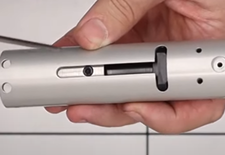
Hammer is retained with a screw under the breech block
16:19 It is unlikely you will need to disassemble the hammer, so the following is largely for information purposes only.
16:26 Locate the lock screw by rotating the hammer inside the housing. Undo the screw using a 2mm allen key.
16:46 Use an M4 bolt and lightly screw it into the side of the hammer housing. Screw in fully then back out a half turn. (16:55) Use a 3mm allen key inserted through the brass component into the back of the hammer. Screw the grub screw in so it emerges from the front of the hammer (17:05).
17:18 You can now remove the two halves of the hammer from the hammer housing. Screw the M4 bolt in further – a couple of turns will do it – and use a flat-bladed screwdriver to unscrew the brass component (17:30). Note that Loctite is applied to this component in the factory so undoing it is only advised if absolutely necessary.
17:44 Remove the M4 bolt so the front half of the hammer can be extracted.
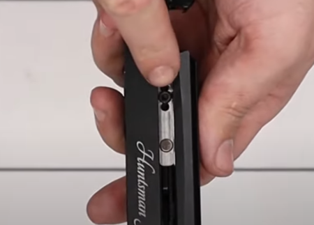
SAFETY DISASSEMBLY
18:04 Remove the bolt from the bottom of the safety housing using a ¼ inch open spanner to loosen the lock nut and then undo the bolt with a 3/32 allen key. This will enable a small anti-tamper pin to be removed. The pin is used to block access to the hammer spring adjuster.
18:30 Use a 1.5mm allen key to remove the screw in the safety cap. This will reveal a spring that can be removed using a pair of tweezers, and a ball bearing (18:41). You may find a small magnet helpful to remove the ball bearing (18:55).
19:01 Use a wide flat-bladed screwdriver do undo the screw in the back of the safety housing. This will allow the two main parts to the safety housing to be separated.
VALVE ASSEMBLY
19:16 Remove the cap from the end of the valve assembly housing using a set of snap ring pliers. Use a pair of tweezers to remove the exposed valve return spring (19:33) and then the valve pin and valve seat (19:37).
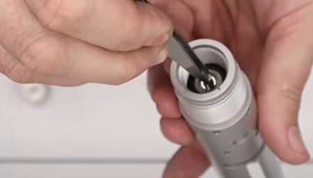
Remove valve and vale seat taking care not to damage the valve seat
19:51 The small brass coloured nut and ‘o’ ring beneath it at the base of the valve assembly can be removed with a long flat-bladed screwdriver.