THE HUNTSMAN REVERE
Assembly Guide

ON THIS PAGE
- Tools you will need
- Installing the valve
- Hammer assembly and installation
- Reassembly and installation of the safety unit
- Assembling the regulator
- Assembling the air cylinder
- Installing the trigger
- Assembling the pellet probe and cocking arm
- Assembling and installing the barrel and shroud
- Mating the top and bottom block
- Power adjustment
- Trigger adjustment
- Installing the stock
INTRODUCTION
Daystate air rifles are engineered to the highest standards, but like anything else, they require repairs and servicing work to be carried out both in and out of warranty.
The aim of this guide and the accompanying video is to help you undertake work on the Daystate Huntsman Revere to address common faults.
Compressed air is dangerous. You should only use this guide if you are a qualified and experienced gunsmith used to working with compressed air. Before you carry out any work on the Daystate Wolverine, or any PCP air rifle for that matter, you must ensure it is not cocked, not loaded and empty of air.
TOOLS YOU WILL NEED (00:28)
- Allen keys: 1.5mm, 2mm, 2.5mm, 3mm, 4mm, 5mm. 1/16, 3/32
- Snap ring pliers
- Long nose pliers
- Open ended 22mm spanner
- 11mm ring spanner
- ¼ open ended spanner
- Triangle anti-tamper removal tool
- Tweezers
- Magnet
- Flat bladed screwdrivers 1.5mm. 3mm, 6mm and 13mm wide
- 2mm and 7mm punch
O rings used in Huntsman Revere
| Huntsman Regal/Revere | Size | IMP or Metric | Shure | LOC | |
|---|---|---|---|---|---|
| 1 | 003 | IMP | N70 | Bolt | .177 |
| 1 | 004 | IMP | N70 | Bolt | .22 |
| 1 | 005 | IMP | N70 | Bolt | .25 |
| 1 | 111 | IMP | Urethane | ||
| 1 | 020 | IMP | N70 | ||
| 1 | 021 | IMP | N70 | ||
| 2 | 118 | IMP | N70 | Regal | |
| 1 | 006 | IMP | Urethane | ||
| 1 | 19 x 2 | M | N70 | ||
| 1 | 008 | IMP | N70 | ||
| 1 | 014 | IMP | N70 | ||
| 1 | 010 | IMP | N70 | Regal | |
| 1 | 006 | IMP | N70 | ||
| 1 | 810 | IMP | N70 | Regal | |
| 2 | 21 x 2 | M | N70 | ||
| 1 | 22 x 2.5 | M | N70 |
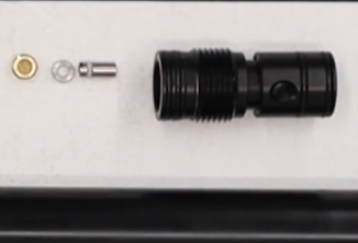
INSTALLING THE VALVE
1:17 Take the small ‘o’ ring and apply a small amount of silicone grease and install it into the base of the block, using a small pair of tweezers to locate and seat it.
1:43 Using a pair of tweezers, take the small brass nut and install it over the ‘o’ ring with the slot uppermost. Tighten using a flat bladed screwdriver.
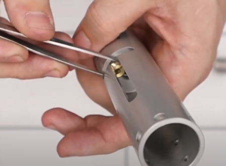
Inserting the brass nut over the firing vale ‘o’ ring
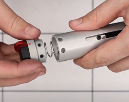
1:58 Add the valve return spring to the boss on the valve cover.
2:08 Apply a small amount of silicon grease to the ‘o’ ring around the outside of the valve seat. Ensure the counter-bored side faces up towards the valve pin. The flat side should face down towards the hammer spring.
2:29 Drop the valve seal into the threaded end of the block with the counter-bored end facing up.
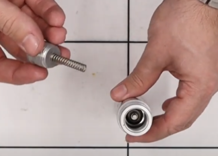
Valve seat and valve assembly
2:40 Use a pair of tweezers to insert the valve pin through the valve seat.
2:53 Locate the valve return spring on the cap over the valve pin and tighten. (2:57) You can look through the upper hole on the block to ensure the spring is aligned over the valve pin. (3:20) Tighten the cap by hand and then with a set of snap ring pliers.
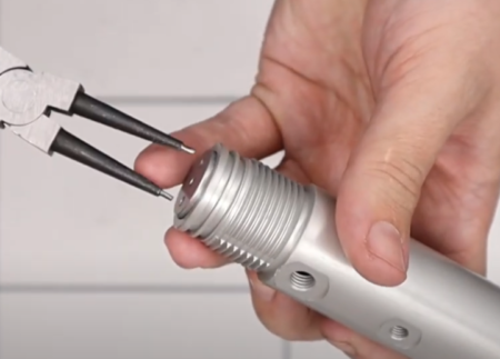
Tightening the valve cap
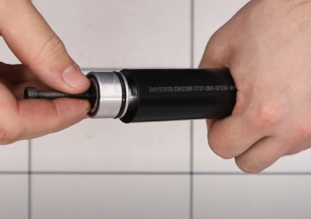
3:32 Take a large allen key and press the valve through the open end of the block to ensure the spring is properly situated.
HAMMER ASSEMBLY AND INSTALLATION
3:48 Insert the hammer weight and into the hammer housing, aligning the two holes.
3:59 Use an M4 bolt to screw into the side of the hammer weight.
4:06 Take the brass screw and place the small spring over the screw. (4:15) Add a small amount of blue Loctite to the brass thread. (4:21) Insert the brass screw into the hammer weight using a flat bladed screwdriver. (4:34) You can now unscrew the M4 bolt so that it does not intrude into the threaded section.
4:50 Take the striking face of the hammer and screw it into the top of the hammer weight. Ensure the flex section protrudes from the hammer assembly and that the allen head side is within the assembly.
5:04 Use a 3mm allen key and insert through the brass screw. Turn the allen key anti-clockwise to screw the hammer into the housing until the grub screw stops. The M4 bolt can then be removed and replaced with the small grub screw using a 2mm allen key.
Correct seating of the hammer
5:40 You can now insert the reassembled hammer into the block, orienting the flat section of the hammer with the top of the rifle block.
5:53 Take the short M3 bolt and install into the hammer through the slot in the top of the block using a 2.5mm allen key. Do not over-tighten as you are screwing into Delrin.
REASSEMBLY AND INSTALLATION OF THE SAFETY UNIT
6:17 Add a small amount of molly grease to the small ball dent and the hole. Wipe a small amount of grease over the housing.
6:40 Take the safety catch and place it on to the component you have just greased, lining up the pin in the safety catch with the hole (6:46).
6:52 Take the screw and add a small amount of blue Loctite to the thread before screwing into the back of the safety unit with a flat bladed screwdriver.
7:10 Apply a small amount of molly grease to the ball-bearing and drop it into the small hole in the black safety catch unit (7:22). Add the spring on top (7:27) and then insert and tighten the grub screw with a 1.5mm allen key. Do not over-tighten as the grub screw simply secures the spring and ball-bearing, ensuring the safety catch rotates (7:41).
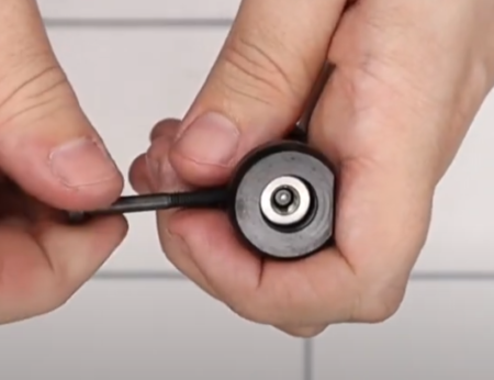
7:49 Install the anti-tamper bar into the hole on the side of the black safety catch and then cap off with the screw (7:59), tightening with a 3/32 allen key and ¼ inch spanner. Note: if velocity is to be adjusted leave the anti tamper bar out for now.
8:12 Reinstall the safety unit into the back of the block by first inserting the hammer spring into the open end (8:18), then take the safety catch unit, orientating the two holes on the safety unit with the two holes on top of the block.
Safety catch orientation
8:41 Insert the two small dog-pointed grub screws on either side of the block.
ASSEMBLING THE REGULATOR
A separate regulator strip and assembly video for the Huntsman Regulator is available here
9:08 Add a small amount of silicon grease the all the internal ‘o’ rings.
9:25 Ensure the Belleville washers are properly ordered on the regulator piston. There are six stacked in pairs. The first two are cupped facing away from the thin end of the piston, the next two pairs are cupped towards the regulator body.
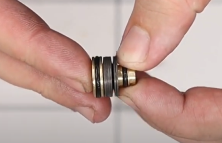
Washer order
09:48 Place the white sealing disc to the top of the regulator piston.
09:55 Push the piston through the middle of the regulator body ensuring the white disc faces the open end of the regulator housing.
10:05 Install the snap ring into the bottom of the regulator housing using a set of snap ring pliers.
10:20 Add the regulator adjuster screw to the top of the regulator housing. Screw it home with a flat bladed screwdriver. Note that in the disassembly video you were advised to take a measurement from the top of the regulator body to the top of the regulator piston. Set the screw to the same distance to ensure the same or similar power setting.
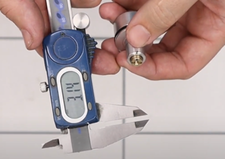
Reset regulator to existing reading
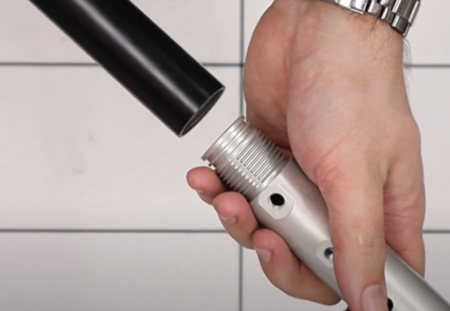
ASSEMBLING THE AIR CYLINDER
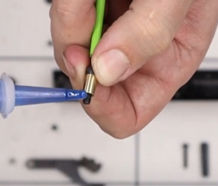
11:01 Take the one-way valve and add a small amount of silicon grease to the ‘o’ ring.
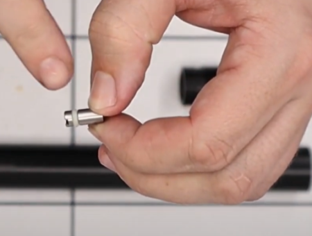
A leak point, this ‘o’ ring need to be kept clean and lightly-lubed with a silicon grease
11:12 Drop the valve into the hole in the component that screws into the cylinder, ensuring the slotted end is uppermost. Push it down with an allen key so it is seated properly.
Filler valve components and correct order
11:20 Take the small spacer and drop it over the one-way valve and then cap off with the small brass nut. Tighten the brass nut with a flat bladed screwdriver (11:30).
11:47 The pressure gauge screws into the threaded end of the component and is tightened with a 22mm spanner.
12:02 Add a small amount of silicon grease to the ‘o’ rings at the other end and then screw the component into the front of the air cylinder (the end without any writing on it.)
12:21 Put a 7mm punch through the fill port hole to enable you to tighten up properly.
12:33 To install the regulator, screw an M5 bolt into the piston via the large end. Apply silicon grease to the ‘o’ ring around the outside of the regulator (12:41) and on the underside into which you have just screwed the M5 bolt.
Regulator replacement
12:52 Install the regulator into the air cylinder. Push it in until it is level with the thread on the inside of the air cylinder (12:59). Screwing the air cylinder on to the valve will locate the regulator (13:03).
Air cylinder replacement. Note the lack of sealing o rings on regulated models
INSTALLING THE TRIGGER
13:15 Take the trigger housing and install the three slot-headed bolts. You find it helpful to use a pair of tweezers to position the bolts.
13:28 Position the housing on the bottom of the block and screw in the slot-headed bolts with a flat-headed screwdriver.
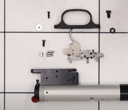
Trigger components in position
13:48 Take the smaller sear. Insert it into the trigger housing aligning the hole in the side of the sear with the uppermost hole in the trigger housing (13:53). Again, you may find a pair of tweezers helpful.
14:08 Insert the pin into the hole, using a pair of tweezers to manipulate the sear into the correct position so the pin captures the sear properly.
14:27 The second, slightly longer sear, is inserted with the screw located in a hole in the first sear (14:36). Align the hole in the sear with the upper of the two holes in the middle of the trigger housing (14:41).
14:58 The trigger blade is installed and retained with a pin through the rear-most hole in the trigger housing (15:06).
15:19 Take the spacer and using a pair of pin nose pliers, place into the remaining hole in the trigger housing just forward of the trigger blade (15:27). Then insert the screw into the counter-sunk side of the trigger housing (15:36) and tighten with a 2.5mm allen key.
15:45 Install the trigger guard. (15:52).
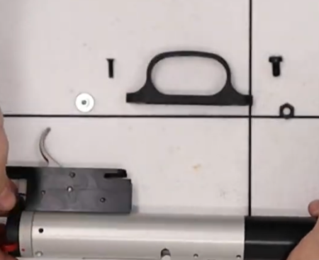
Trigger guard components
Take the nut and locate it under the hole at the front of the trigger guard, insert the larger of the two screws and tighten (but not fully) with a flat bladed screwdriver. (16:12) insert the screw at the back of the trigger guard. Locate the trigger guard to ensure free movement of the trigger blade and tighten both screws (16:17).
16:21 To install the stock bolt housing, take the large hex shaped but and the grub screw. (16:25) insert the grub screw into the hole in the underside of the block using a 3mm allen key. (16:35) Screw the hex nut over the top of the grub screw. Use an 11mm spanner to fully tighten.
16:45 Screw the regulator gauge into the hole forward of the stock retainer nut. Ensure the thinner of the two doughty washers is bottom most on the thread, then the spacer, then the second doughty washer (16:52). Tighten the gauge with a 22mm spanner (17:00).
ASSEMBLING THE PELLET PROBE AND COCKING ARM
17:15 Add smear of molly grease to the outside of the pellet probe and insert into the back of the top block (17:27), thin end first. (17:38) Ensure the counter-bored hole in the pellet probe is oriented so it is visible through the slot in the bottom of the top block.
17:45 Apply a small amount of blue Loctite to the thread on the cocking dog. (17:54) Screw the cocking dog into the counter-bored hole in the pellet probe using a 3/32 allen key.
Important to apply thread lock adhesive to the cocking dog
18:07 Take the small cover piece and orientate it so the longer end of the slope faces the bottom of the block and align with the rear-most hole on the underside of the top block. (18:20) Take the screw that has a smaller head than the others and insert into the hole, tightening with a 2mm allen key.
18:36 Turn the top block over so the top is facing you. (18:41) You will need to decide which side of the top block you want to install the cocking arm into. (18:48) Apply a light coat of molly grease to both sides of the hole at the rear of the cocking arm and the push the bush through the hole (18:54). Wipe off any excess grease.
19:07 Insert the cocking arm into the top block, orientating the hole on the rear of the arm with the hole at the rear of the top block. (19:16) Put the long screw through the hole and tighten with a 2.5mm allen key.
19:30 Take the front section of the cocking arm and line it up with the pellet probe through the slot in the top block. (19:36) From the other side of the slot, insert the screw into the middle of three holes on the pellet probe. Tighten with a 2.5mm allen key.
19:53 Add the cover plate to close the slot on the top block that you have not used to install the cocking arm. (20:01) Secure with a screw inserted into the hole on the top of the block using a 2.5mm allen key.
20:13 The drop-down handle on the cocking arm is attached by inserting a screw through the cocking arm and into the handle from the top then tightening with a 2.5mm allen key.
ASSEMBLING AND INSTALLING THE BARREL AND SHROUD
20:28 The barrel is installed into the front of the block, ensuring the retention holes are uppermost and aligned with holes in the block.
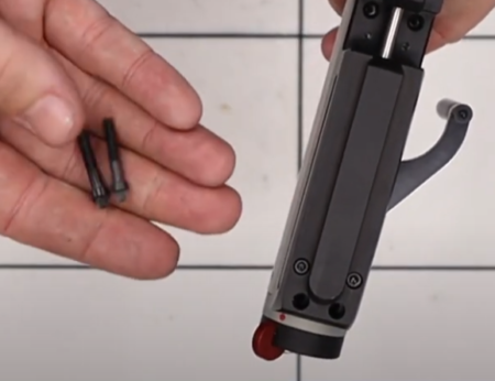
20:32 There are four retaining grub screws – two long and two that are shorter. The longer grub screws are inserted on the top of the block and the shorter ones go in the bottom of the block.
20:50 From the bottom of the block, ensure the transfer port is aligned with the rear of three holes in the block, and that the dimples in the barrel are aligned with the forward most two holes. (20:52) insert the shorter grub screws into the forward two holes and tighten with a 2mm allen key. (21:00) Turn the block over and screw in the two longer grub screws.
21:10 Apply a small amount of silicon grease to the ‘o’ ring on the barrel end carrier and insert into the muzzle end of the shroud (21:17). Place the spacer ‘o’ ring over the barrel carrier (21:24), then screw on the ½ inch UNF end cap and tighten with a wide flat head screwdriver. Finally, screw on the thread protector (21:43).
21:49 Turn the block and barrel over so the bottom is uppermost and slide the shroud over the barrel (21:52). (22:05) Insert the two securing grub screws and tighten with a 1/16 allen key.
MATING THE TOP AND BOTTOM BLOCK
22:39 Apply a small amount of silicon grease to the two ‘o’ rings. (22:43) The first ‘o’ ring is inserted into the recessed hole in the underside of the bottom block. Ensure it is properly seated. (22:56) The second ‘o’ ring is dropped into the hole in the bottom of the top block at the base of the barrel.
23:04 The brass transfer port is pushed into the hole in the bottom of the top block.
23:12 Align the top of the bottom block with the bottom of the top block ensuring the two halves line up with the transfer port.
23:25 Turn the block so you can insert the two long allen screws into the forward most two of the four holes just forward of the breech.
23:35 Take the triangle headed anti-tamper bolts and insert them in the two holes at the back of the top block just above the safety catch.
Anti tamper bolts fitted to UK spec rifles only
23:46 Insert the two slot headed screws into the holes at the bottom of the breech.
23:54 Tighten all bolts and screws up using a 2.5mm allen key, the Daystate anti-tamper tool and a flat headed screwdriver.
24:30 Slide the barrel band slides over the muzzle and ease it over the ‘o’ rings by the air fill pressure gauge. (24:51). Push the air fill pressure gauge over the gauge until it is held by the ‘o’ rings.
24:55 Secure the barrel band by screwing in the three M3 grub screws using a 1.5mm allen key.
POWER ADJUSTMENT
Full video can be viewed here.
2:10 With the rifle full of air and pointing in a safe direction, cock the rifle
2:30 Insert a long 3mm allen key into the hole at the back
2:38 Rotate the hammer until the hammer locking screw is visible through the lower action inspection hole loosen the locking screw
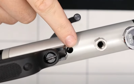
2mm hammer locking screw lined up
3:36 Making small adjustment wind in the 3mm allen key to increase power, wind out to decrease power, checking on a chronograph between adjustments. Note. Its important not to over-adjust to the point that the centre core of the slingshot hammer is touching the valve stem with the hammer at rest. A further note is that 40 ft/lbs versions use a solid hammer which will rest on the valve and adjust in the opposite direction i.e. in to increase power out to reduce. Similarly, the hammer must not be over adjusted or a drastically reduced shot count will result.
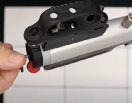
Allen key power adjustment
TRIGGER ADJUSTMENT
Full video can be viewed here.
Allen Key Size: 1.5 mm
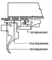
Trigger adjustment
1st adjustment: Adjusts the second stage weight setting. Remove the locking screw. To increase the weight, turn the screw anti-clockwise, and clockwise to lighten the weight. IMPORTANT. Do not adjust this screw too far clockwise as the gun will not cock.
2nd adjustment: Enables you to set the angle that the trigger blade sits in the trigger block (factory setting is approximately 90°). If this is adjusted then the 3rd adjustment will have to be altered.
3rd adjustment: This screw will adjust the first stage travel. Turning it anti-clockwise will increase the travel and clockwise will decrease the travel.
NOTE: AFTER ADJUSTING THE TRIGGER IT MAY BE NECESSARY TO ADJUST THE SAFETY CATCH ACTIVATOR SCREW IN OR OUT – TO ENSURE SAFE OPERATION OF THE SAFETY CATCH.