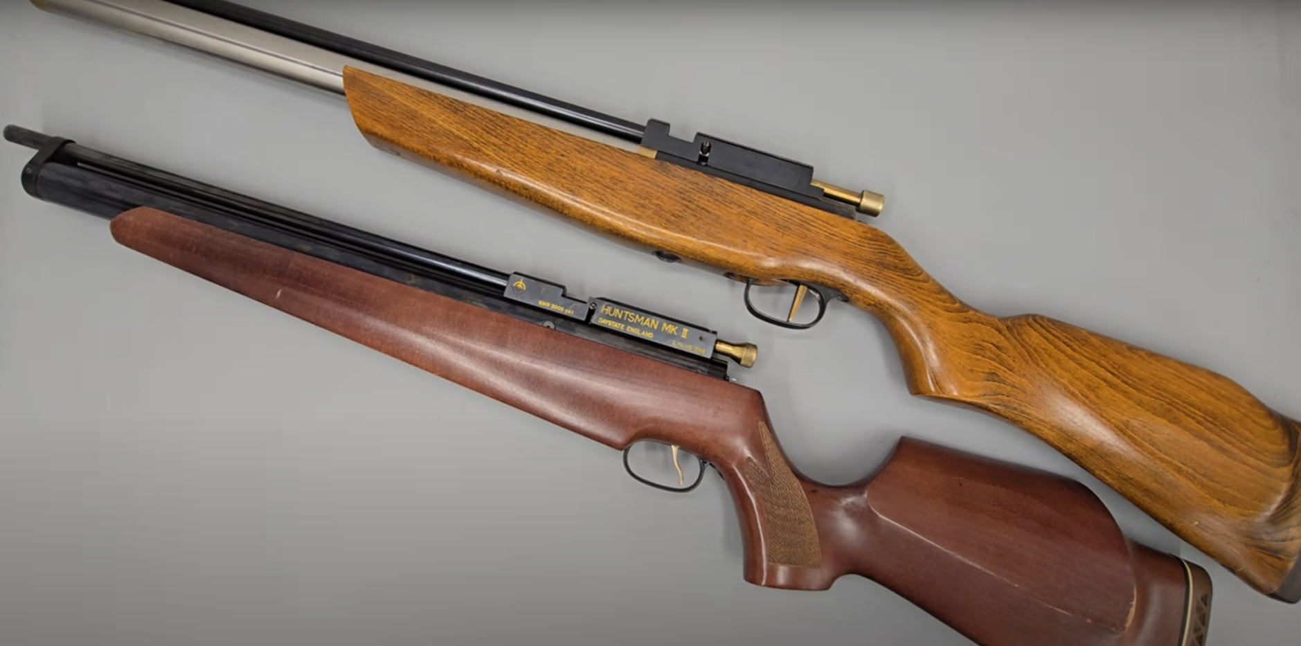
THE HUNTSMAN HH & MK2
Disassembly Guide


INTRODUCTION
Daystate air rifles are engineered to the highest standards, but like anything else, they require repairs and servicing work to be carried out both in and out of warranty.
The aim of this guide and the accompanying video is to help you undertake work on the Daystate Huntsman models. HH and Huntsman Mk II rifles are shown as a start and finish of the type examples. A system of rolling development was carried out on the Huntsman rifle from the early HH made in 1980, then the Midas from 1983 through the MK1 and onto to the MK2, last made in 2003, so some variation will be seen, but principles remain the same across all models. Later Huntsman Classic, Regal and Revere models are covered in separate videos.
Compressed air is dangerous. You should only use this guide if you are a qualified and experienced gunsmith used to working with compressed air. Before you carry out any work on the Daystate Pulsar, or any PCP air rifle for that matter, you must ensure it is not cocked, not loaded and empty of air. Degassing both rifles is achieved by dry firing them until the air supply is expended.
HISTORY
There has been a Huntsman in the Daystate range since the early 1980s. Only the name and visual similarity remain the rifle having developed enormously over time. Introduced as the Huntsman HL (Huntsman Low) and Huntsman (Huntsman High). This was replaced in the mid 80s by the Huntsman Midas, named for its brass-coloured cylinder that had replaced the stainless steel cylinder on the earlier rifles. In 1987 the Huntsman MK1 was introduced as a project to reduce costs in the original rifle. By 1989 this version proved so popular it eventually obsoleted the earlier rifle. In 1995 a mark 2 version was introduced. The MK2 can be subdivided into two types of the earlier rifles using many mark 1 parts with the later rifles using a thinner and lighter air tube. The Huntsman MK2 was discontinued in 2002. In 1997 a version of the Huntsman was introduced called the Harrier (later Harrier X and X2) which had many components from the Huntsman MK2. This guide can be used for all Harrier and Merlyn variations. In 2007 the Huntsman Classic was introduced being itself superseded by the Huntsman Regal in 2013. A separate repair guide is available for the Regal and the subsequent Revere.


TOOLS YOU WILL NEED
- Allen keys: 1/16, 3/32, 3/16
- Spanners: 3/8, 1/2, adjustable
- Flat bladed screwdrivers: 3, 4, 6mm
REMOVING STOCKS
1:35 The stocks are removed by removing the stock bolts on the underside of the stock using a 3/16 allen key
Remove the stock with a single 3 16 allen key
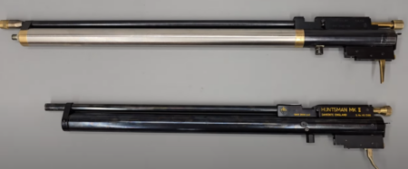
SEPARATING THE TWO HALVES OF THE RIFLES
03:38 Huntsman HH
03:51 The bolt is removed by removing the cocking dog in the side using a flat bladed screwdriver to remove the cocking dog screw from the left side of the rifle behind the breech. This will allow the bolt to be pulled free (04:12)
04:30 Remove the slotted grub screw from the front of the barrel band using a flat bladed screwdriver.
Remove this screw from barrel support
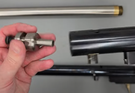
04:50 Unscrew the thread adapter on the muzzle. Note that Loctite will have been used at the factory so you may need to apply some heat to loosen.
Remove adaptor if fitted
05:15 Remove the four securing bolts from the top of the main block. The two forward-most bolts are removed using a 3/32 allen key. (05:27) The two at the back are removed using a flat bladed screwdriver.
05:37 With the four bolts removed you will be able to lift the breech block and slide the barrel from the barrel band.
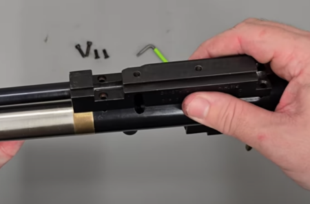
Remove 4 screws and lift away breech block
06:40 Huntsman Mk II
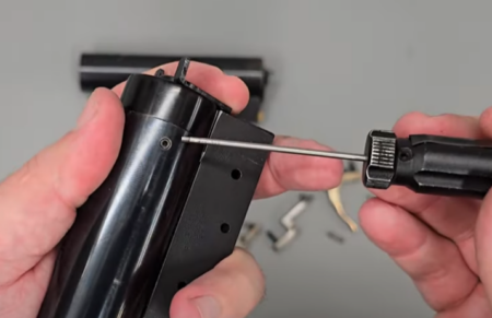
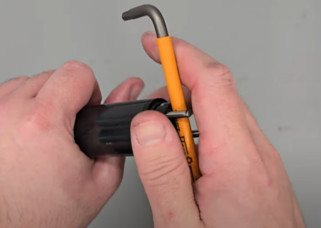
06:47 Remove the barrel band from the end of the cylinder by using a 1/16 allen key to remove the three securing screws. This will allow the barrel band to be pulled off.
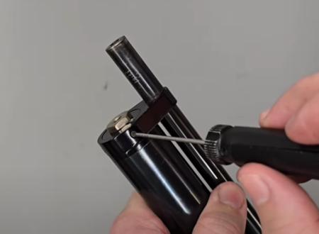
Remove front barrel support screws
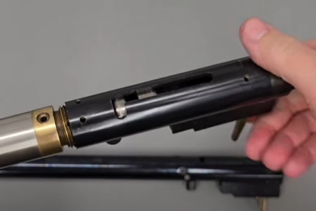
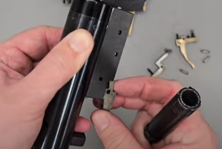
07:10 The two halves of the block are separated by removing the four bolts at the top of the block using 3/32 allen key. This will allow you to lift the breech block and barrel off the bottom of the action. Take care to not lose the small brass transfer port piece on the underside of the breech.
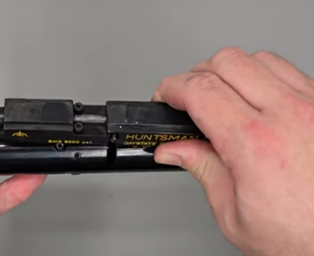
Remove the 4 screws and lift off the breechblock
Remove 4 screws securing the breech block
Take care not to lose the transfer port or n008 ‘o’rings
08:35 The bolt is removed by first removing the spring ball detent in the side just forward of the bolt by loosening the grub screw using a 1/16 allen key. Note that the screw may be held in with a small amount of Loctite.
08:56 Beneath the grub screw is a small spring. Underneath the spring is a ball bearing. You may need to use a magnet to extract the ball bearing.
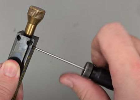
Remove bolt detent locking screw
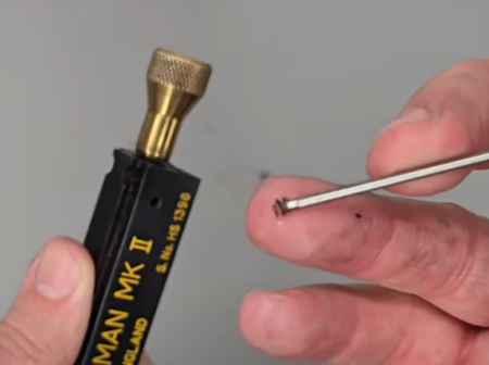
Do not lose the small spring

All the parts from detent locking screw
09:45 The cocking dog is removed from the side of the rifle using a flat bladed screwdriver. Note: this may be held in place with a small amount of Loctite and you may need to apply heat.
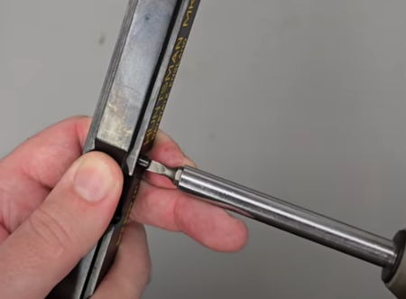
Removing cocking dog, slotted on low powered rifle and allen headed on high power
10:00 The cocking bolt can be pulled from the back of the action.
DISASSEMBLING THE TRIGGER SAFETY AND HAMMER SPRING ASSEMBLY
10:37 On the Huntsman HH it is possible to remove the trigger and hammer assembly as one unit simply by unscrewing it from the air cylinder by hand. (10:55) This will also enable you to tip out the hammer and hammer spring.
On the HH there is a single transfer ‘o’ ring
Unscrew rear body
Removing hammer assembly allows access to the power adjuster in the face of the hammer
11:10 The process is slightly different from the Huntsman MK II.
11:17 The trigger assembly is removed by first removing the three pins staring with the rearmost pin first, the middle pin and finally the forward-most pin.
11:28 Use a small punch or similar to push the pins through. Take care to not lose the small springs in the trigger components.
Remove the three trigger components noting spring positions
11:45 To remove the hammer and hammer spring you will need to remove the safety cap at the rear of the action. This is achieved by removing the two securing grub screws using a 1/16 allen key. As you remove the screws keep hold of the safety cap as it will be under light tension from the hammer spring.
12:09 Allow the cap to come away from the rear of the action. (12:15) The hammer spring can now be removed followed by the hammer.
Remove the rear cap noting to hold cap against spring pressure
DISASSEMBLING THE SAFETY CATCH CAP
13:13 Grip the components firmly as it is possible a ball bearing will spring free.
13:30 Undo the large screw with a flat bladed screwdriver, holding on to the component at the rear.
13:50 The ball bearing is not captive on the Huntsman MKII and can be removed.
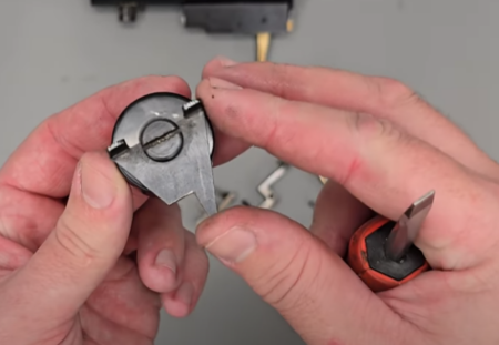
Rear safety has a spring and ball that is easily lost if safety is moved out of the stock
13:57 On the Huntsman HH, the ball bearing is captive and cannot fly out. The end cap on the Huntsman HH differs from that on the Huntsman MK II only in the fact that it screws on to the rear of the action rather than being pressed into it.
Rear cap on HH unscrews
14:23 Tio remove the Huntsman MK II safety cap, use a 1/16 allen key to remove the grub screw and unscrew the cap.
AIR CYLINDER DISASSEMBLY
14:55 Huntsman HH cylinder
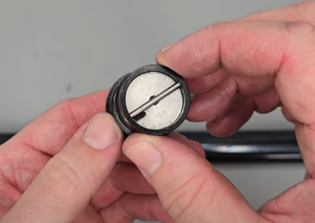
15:00 Use a large screwdriver or similar and depress the valve to ensure all air has been removed.
Press on the firing valve to check there is no air left in the air cylinder
15:30 To remove the caps at either end you will likely need to grip the cylinder in a vice with soft jaw protection.
15:33 The rear valve end cap can be removed by inserting a tight-fitting punch or similar in the transfer port for leverage. The cap can then be unscrewed.
16:00 It is recommended that you use some electrical tape or similar to mark the valve end of the cylinder as the two ends will look similar with the caps removed.
16:21 Unscrew the fill end cap from the cylinder.
Using a tommy bar, unscrew the firing valve
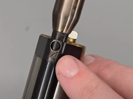
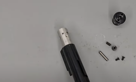
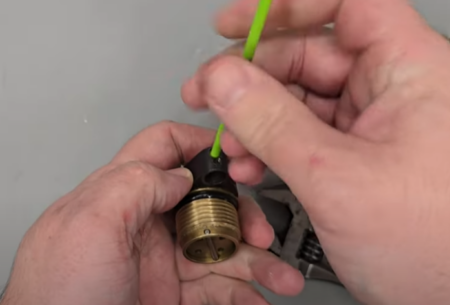
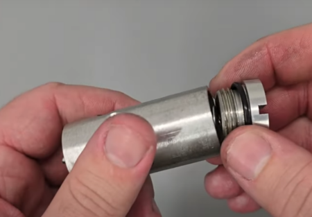
16:40 On the Huntsman MK II cylinder, first thing to do is remove the cap from the muzzle end of the cylinder by removing the fill adapter using an adjustable spanner.
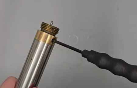
Please note: the accompanying video shows a blanking nut as the rifle is a demo rifle for use at shows. Rifles have been fitted with different fitments over production with FTR and later rifles fitted with a Foster fit valve.
A cross pin retails the filler valve plug
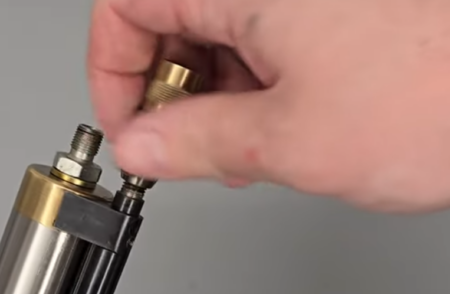
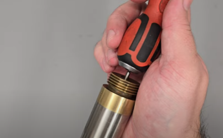
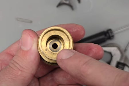
17:07 To remove the cap, insert a couple of 4mm pins into the two holes and then use a large allen key or similar between the two pins to unscrew.
A special removal tool can be substituted by two pins
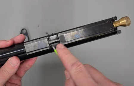
17:42 Crack loose the nut at the bottom of the cylinder using an adjustable spanner.
17:52 Use a flat headed screwdriver to remove the stud screw that has been revealed.
18:00 Use a 3/32 allen key to remove the two screws on either side.
18:09 Push the pin out using a punch.
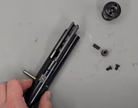
With all side screws removed the cross bar can be drifted out
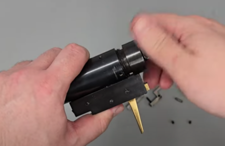
18:28 The valve can be removed from inside the rifle by inserting a rod – something like a broom handle that won’t cause any damage – into the muzzle end of the cylinder to push the valve free.
The valve can be pushed out using a long dowel or screwdriver
VALVE DISASSEMBLY
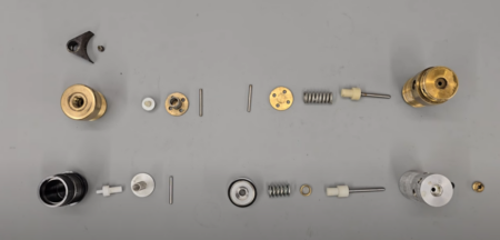
The filling and valve components show for the 2 models
19:11 Huntsman HH
19:17 Remove the fill adapter from the end of the fill valve using an adjustable spanner.
Please note: the end cap may look different on your rifle as many different fittings and adaptors were used.
19:48 Use a 3/32 allen key to remove the screw from the barrel band and lift off the barrel band.
Removing the barrel support from the HH
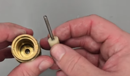
20:04 To remove the one way vale from the cap first depress the plunger at the bottom end so you can push out the pin using a small allen key or similar.
Check for pitting of the sealing area which will need to be polished clean if necessary
20:18 The spring will then fall out from the bottom of the cap.
The front filling valve for the HH is similar to the MK2
20:22 The one way valve can then be pushed out from the other end of the cap.
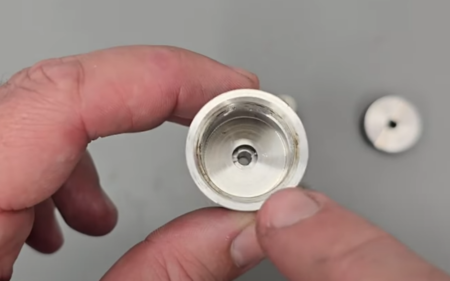
The filling valve sealing face needs to be flat and clean
21:00 The firing valve on the is removed in a similar way by first depressing the plunger to and then pushing out the pin to remove the cap. This will allow the firing valve to be tapped out.
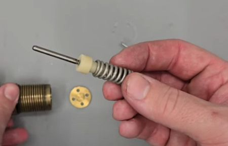
Removing the firing valve
21:18 The firing valve and valve return spring can be separated by pulling them apart.
The valve and valve sealing face need to be clean and unpitted
22:15 Huntsman MK II
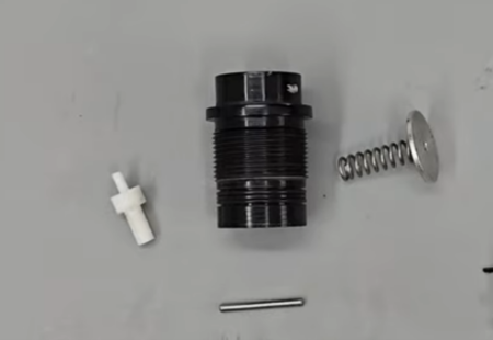
The front filling vale on the MK2
22:17 The fill valve disassembly is similar to that of the Huntsman HH. First depress the plunger and push out the pin. This frees the cap so the fill valve taps out.
M2 filling valve seal is prone to leaking if the valve face is not clean and flat
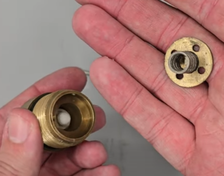
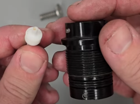
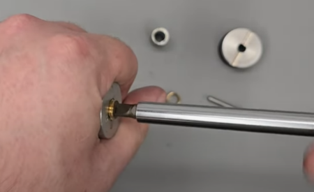
23:18 Unscrew the back cap taking care to not lose the valve return spring beneath.
23:32 The valve can then be pulled free. The valve spring spacer can also be separated from the valve spring.
Unscrewing the valve body to remove the valve. the ‘o’ ring shown is a common leak area and must always be replaced
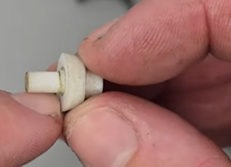
This is what a good M2 valve face looks like
23:47 The valve stem seal can be removed using a flat headed screwdriver. Note: if there is any sign of corrosion in this area especially on brass vale bodys, do not attempt to remove the valve stem seal as the threads can be damaged during removal and replacement valve body’s are unavailable. If in doubt, do not replace this seal as it is seldomly in need of replacement.
Take care when removing valve pin retaining screw, if in doubt do not replace