THE ALPHA & DELTA WOLF
Disassembly Guide

INTRODUCTION
Note: this guide relates to Alpha and Delta Wolf rifles. For simplicity Delta Wolf is referred to throughout.
Daystate air rifles are engineered to the highest standards, but like anything else, they require repair and servicing work to be carried out both in and out of warranty.
The aim of this guide and the accompanying video is to provide instruction on how to re-assemble the Daystate Delta Wolf. The rifle in the video and to which this guide relates is a sub 12 ft/lbs Delta Wolf. The information contained also applies to FAC versions of the rifle as well as the Alpha Wolf.
Compressed air is dangerous. You should only use this guide if you are a qualified and experienced gunsmith used to working with compressed air. Before you carry out any work on the Daystate Delta Wolf, or any PCP air rifle for that matter, you must ensure it is not cocked, not loaded and empty of air.
It is advised that you disconnect the battery and leave the rifle overnight to ensure any charge in the capacitors to discharge fully.
A number of additional videos, not used in this guide, have been made by the company to aid servicing and repair:
Daystate Alpha & Delta Wolf Valve Installation Information.
Daystate Alpha & Delta Wolf regulator service and repair
Alpha and Delta Wolf barrel and chrono servicing
Daystate Delta Wolf & Alpha Wolf – Chrono Tube Maintenance
Daystate Alpha & Delta wolf – How to remove and refit the shroud and chronograph assembly.
HISTORY
The Daystate Delta Wolf represents a leap forwards for daystate moving to a completely new format and electronics package. Designated as AVT (Advanced Velocity Technology), a modular system allows for fast interchange of components giving more options for shooters, and making assembly of different models using common components fast and straightforward. An integral regulator by specialist HUMA-Air added to a chronograph controlled electronic firing system, and a quick change barrel allows for fast calibre and barrel and power changes all of which can be controled in the field by the shooter. Delta Wolf introduced in March 2020 an the Alpha Wolf version in 2022. Various sub models have been released including a smart version which removes the chronograph and a performance version that adds many accessories as standard.


TOOLS YOU WILL NEED
- Allen keys: 0.89, 1.5, 2, 2.5, 3, 4, 5 mm
- 19mm ring spanner
- Open ended 22mm spanner
- Deep 10mm socket
- Tweezers
- Plastic ‘o’ ring pick
- Metal ‘o’ ring pick
- Torx T6 driver
- PHO driver
- Flat bladed screwdriver 3 and 5mm side
- Snap ring pliers
- Daystate tools:
- Regulator removal tool
- Valve removal tool
O rings used in Delta Wolf
| Delta Wolf | Size | IMP or Metric | Shure | LOC | |
|---|---|---|---|---|---|
| 2 | 13 x 15 | M | N70 | ||
| 1 | 14.5 x 3 | M | N90 | ||
| 1 | 004 | IMP | N90 | ||
| 2 | M12 | M | Bonded washer | ||
| 3 | 1/8 | BSP | Bonded washer | ||
| 4 | 15 x 2 | M | N70 | ||
| 1 | 10 x 15 | M | N70 | ||
| 2 | 006 | IMP | N70 | ||
| 9 | 617 | IMP | N70 | ||
| 1 | 007 | IMP | N90 | ||
| 1 | 93 x 24 | M | N90 | ||
| 1 | 17 x 1.5 | M | N70 | ||
| 2 | 813 | IMP | N70 | ||
| 1 | 4 x 15 | M | N70 | ||
| 1 | 4.1 x 1.6 | M | N70 | .177 | |
| 1 | 009 | IMP | N70 | .22 | |
| 1 | 6.1 x 1.6 | M | N70 | .25 | |
| 1 | 75 x 15 | M | N70 | .30 |
DE-GASSING AND REMOVING THE BATTERY
00:59 Ge-gassing the rifle is achieved by simply undoing the bottle.
01:15 You will need to ensure there is no air left in the plenum (regulator chamber). This can be done by checking the read out on the screen. If it shows a reading for reg pressure you will need to empty the regulator. This can be achieved by dry firing the rifle. Once empty, the screen will read ‘0 bar reg’ (01:36).
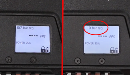
Ensure the regulator chamber is at 0
01:59 The battery is accessed by turning the rifle upside down and undoing the battery cover latch. This will allow the rear of the butt section to slide off (02:06).
02:14 The battery can now be pulled out of the cavity in the butt.
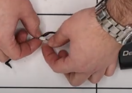
02:20 Disconnect the battery by pulling the switch wires free from the block. Take care to grip the plastic connector rather than the wires themselves.
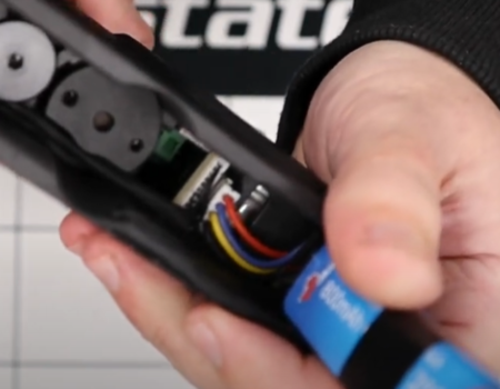
Take care to grip the plastic connector rather than the wires
02:55 It is recommended that you leave the rifle overnight to allow any change in the capacitors to fully dissipate.
BARREL AND SHROUD REMOVAL
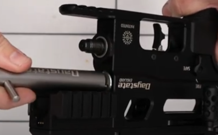
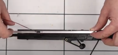
03:15 The barrel is removed by loosening the grub screw forward of the breech using a 3mm allen key. The barrel and shroud will slide out as one.
Removing the barrel assembly
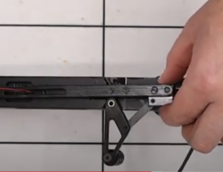
03:41 The carbon fibre shroud is removed by removing the two grub screws using a 2.5mm allen key. This will allow the shroud to slide off the barrel, revealing the chronograph.
03:58 The chronograph assembly is removed from the barrel by removing the two grub screws at the back of the shroud back boss using a 2.5mm allen key.
Chronograph assembly
04:13 Grip the chronograph and unscrew it from the barrel.
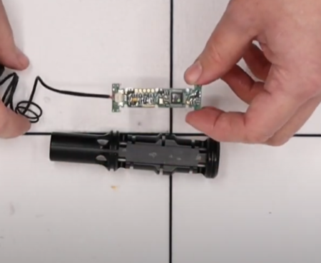
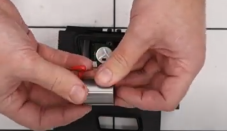
04:45 The chronograph circuit board can be removed from the chronograph housing by first removing four ‘o’ rings using a plastic pick.
05:15 With the ‘o’ rings removed, the circuit board can be lifted off the housing. Take care to not lose the clear plastic insulating cover between the circuit board and the housing.
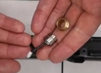
05:35 The clear plastic tube that runs through the centre of the chronograph can be removed by first undoing the brass nut at the end (05:40) using a flat headed screwdriver.
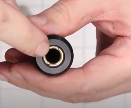
Plastic tube is replaceable
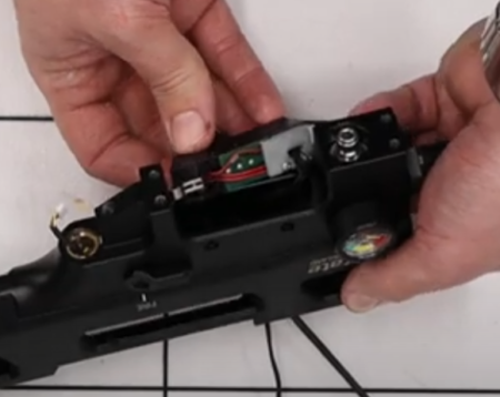
REMOVING EH ELECTRONIC HOUSING
06:33 Remove the top bolt accessed through the back of the butt using a 3mm allen key. This will allow you to tease up a wire and then remove it, taking care to grip the connector rather than the wires (07:11).
Remove this bolt before disassembly to help with wire removal
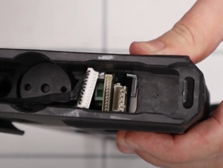
Detachment of the main control wire
07:31 Remove the cheekpiece from the top of the butt by loosening the two screws with a 2.5 mm allen key. The cheekpiece then slides off, giving you access to four bolts underneath (07:42).
07:45 Use a 3mm allen key to remove the bolts.
07:57 Remove the grub screw below the breech using a 3mm allen key. This will allow the butt block to slide off the main block of the rifle, making sure the wires and connectors in the back of the butt do not catch.
08:32 Take care to no lose a spring in the front of the butt block.
DISASSEMBLING THE ELECTRONIC/BUTT BLOCK
08:47 The screen is removed by undoing the two bolts using a 2mm allen key. Take care to not pull the scree off as it will still be connected internally. To remove the screen completely you will need to disconnect the ribbon cable (09:01) by pulling down on the two grey connection tabs.
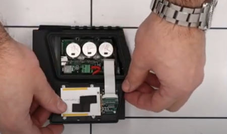
Display screen and connecting ribbon
09:21 Loosen the two coil wires using a small flat head screwdriver. Pick out the coil wires using a plastic pick.
Disconnecting the coil wires
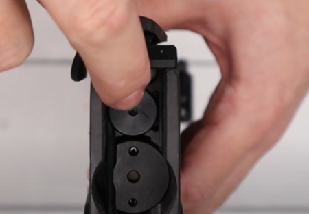
09:46 Remove the screws holding in the back block using a T6 torx bit. Take care to not lose the insulating pads below the screws as you remove them.
10:11 Use a pair of tweezers to remove the insulating pads.
10:30 Use a pair of snap ring pliers to remove the coil nut from the rear of the butt block.
11:02 Tip the butt block so the hammer slides out and a black spacer.
11:13 The coil is removed by lifting the wires out of the way and pushing the coil out of the back of the butt block.
Coil assembly
11:42 Two metal rings can also be tipped out of the back of the butt block. Note the newer versions have one, thicker ring.
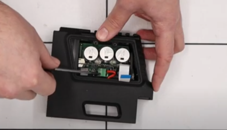
12:00 The circuit board is removed by lifting it out of the butt block at an angle. You will need to remove a connection (12:11) at the back, again taking care to grip the connector rather than the wires. Ideally, store the circuit board in an anti-static bag.
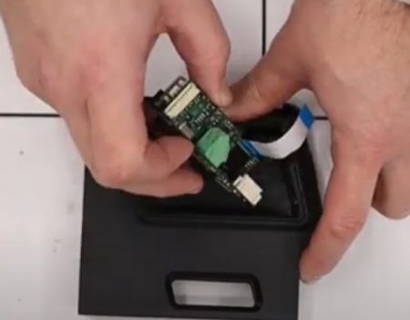
PCB removal
12:48 The battery catch is removed by removing a screw in the catch itself using a 2mm allen key and then sliding the plastic catch out taking care to not lose a small spring. The spring can be removed with a pair of tweezers.
REGULATOR REMOVAL AND DISASSEMBLY
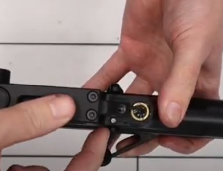
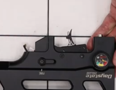
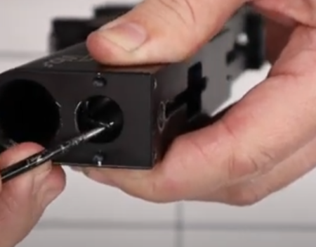
Important note: To ensure the rifle is empty of air, despite removing the air bottle and dry firing, it is recommended that you carry out a manual degassing check. To do this, depress the valve at the front of the block with your finger (13:34). If no air escapes, you are safe to proceed.
Checking the valve is depressurised before removal
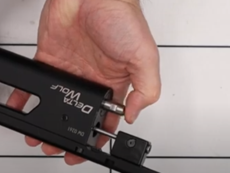
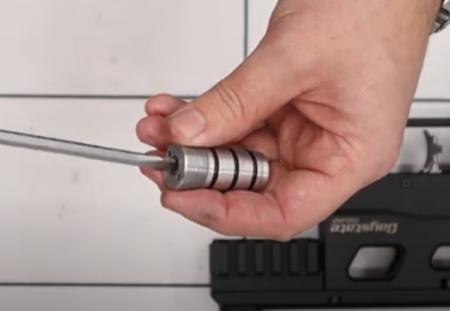
14:53 Use the Daystate regulator removal tool and locate the pins into the holes in the aluminium cap on top of the regulator at the front of the block and rotate anti-clockwise. If you do not have the removal tool, you can use a set of snap ring pliers instead.
Regulator removal
15:05 Remove the adjuster screw using a flat bladed screwdriver.
Regulator strip and adjustment
15:18 Put your finger over the hole you have just created and screw in an M4 screw into the piston in order to pull the regulator out.
15:58 Tap the regulator housing to remove the white plastic sealing disc.
The regulator components
A separate regulator strip and assembly video for the Regulator is available here
VALVE REMOVAL AND DISASSEMBLY
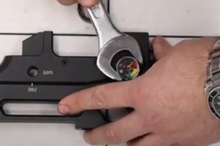
17:02 Use the Daystate valve removal tool and 19mm ring spanner, or a set of snap ring pliers and locate in the two voles in the valve at the back of the block and turn anti-clockwise.
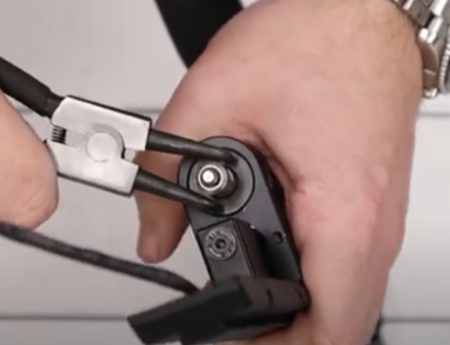
Firing valve removal
17:47 The valve should pull out of the block. If necessary, you can put the valve stem in a pair of soft jaw pliers.

The valve removed
18:07 Two sealing ‘o’ rings can be removed.
18:20 The two halves of the valve can be separated by twisting the back and front in opposite directions.
18:43 The valve pin can then be pulled out along with the valve return spring and a cup spring guide.
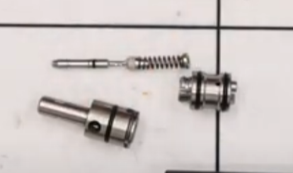
The valve stripped
REMOVING THE SCOPE RAIL AND PISTOL GRIP
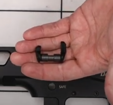
19:41 The pistol grip is removed by first popping the cover at the bottom of the grip using an allen key or similar (19:43) to expose the bolt that can be removed with a 5mm allen key. Make sure you do not lose the small spring under the grip.
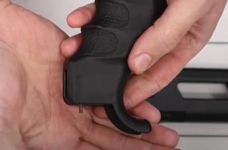
Take care not to loose the safety spring
The safety dowel
20:17 Remove the small pin at the base of the safety catch by tapping the block into your hand.
20:34 Remove the scope rail by loosening the four bolts at the base of the Picatinny rail using a 3mm allen key. The rail will then slide off.
REMOVING TOP RAIL AND COCKING LINKAGE
20:50 Loosen the two rearmost screws using a 3mm allen key to remove the front block. Make sure the front block does not fall and damage an internal electrical connection. (21:15) disconnect the connection by holding the plastic connectors.
21:34 Remove the remaining six screws on the top of the block using a 3mm allen key. Note that the four outer screws are the same length and the two screws in the middle are slightly longer.
22:01 The top rail can now be lifted off the block. Take care to not catch the electrical connections below.
22:17 Remove the cocking lever blanking plate.
22:20 Remove the top wire from the aluminium channel.
22:39 Disconnect the small connector at the front of the channel, taking care to grip the plastic connectors and not the wires.
Carefully disconnecting wire connector
23:21 Remove the two screws holding the aluminium channel in place using a flat headed screwdriver. Take care to not damage the wires.
23:35 When lifting the aluminium channel take care to not lose the two spacers on the screws.
24:01 Tease the wire through the aluminium channel.
Removing top channel
24:13 The cocking arm assembly can be pulled back and lifted off the top of the block, threading the wire with the cocking indicator switch through the slot.
Removing the cocking arm
25:21 The plastic wire guide can be removed by pushing if from below by placing a finger through the side of the block.
TRIGGER AND SAFETY REMOVAL
25:52 Remove the bottom rail below the trigger by removing the four screws using a 3mm allen key.
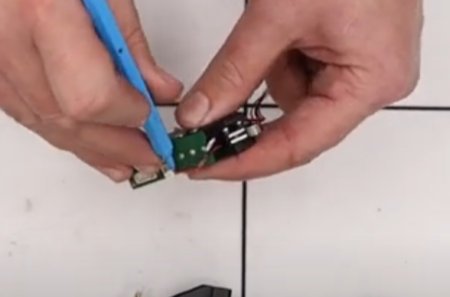
26:08 To remove the trigger and pressure sensor unit, first pick out the wire using a plastic pick and separate the connector, pulling on the plastic connector block rather than the wires. This disconnects the pressure sensor.
Pressure sensor
27:38 The trigger unit is removed by removing the four screws from both sides of the main block just above the trigger using a 2mm allen key. The trigger unit can then be pulled from the block (27:56). Ensure the wire at the top of the block is not caught. Feed the pressure sensor wire through.
Trigger unit removal
28:40 Remove the two screws on the side of the trigger circuit board using a cross head screwdriver.
29:10 Disconnect the main wiring harness from the rear of the trigger unit circuit board. The circuit board can now be fully removed.
Trigger unit showing the safety switch (left of image)
29:50 The remaining wire can now be removed from the block.
30:04 Remove the two screws at the top of the trigger unit using a small cross head screwdriver.
30:14 Remove the pressure sensor wire from the trigger unit circuit board.
30:22 Remove the safety wire from the trigger unit circuit board.
30:33 The circuit board can be removed from the trigger unit.
Trigger unit
30:49 The pressure sensor wire can be pulled free of the trigger unit.
31:00 Remove the safety switch by undoing the remaining two screws with a small cross head screwdriver.
31:20 The trigger blade is removed from the trigger unit by using a plastic pick to push a small pin from a rearmost of two small holes at the front of the trigger unit and then removing fully with a pair of tweezers. The trigger blade will now pull free. Take care not to lose the small spring.
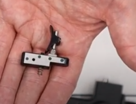
Trigger
SAFETY SWITCH REMOVAL
The safety switch should not be removed until the trigger unit has been removed. Failure to do this may damage the safety shoe.
33:57 The safety switch is removed by using a 2mm allen key. Removing the screw from one side will allow the switch to be removed from the other.
Safety tabs are reversable
FILL PORT REMOVAL
34:31 Use a 10mm deep socket to remove the fill valve on the underside of the block. Take care to not lose the doughty washer beneath the valve.
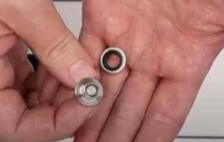
The filling connector removed
BLOCK ‘O’ RING REMOVAL
36:52 Use a metal pick to remove the two sealing ‘o’ rings in the barrel cavity.
Barrel cavity ‘o’ rings can be dislodged if the rifle is fired with the barrel removed
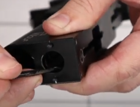
Barrel cavity ‘o’ ring removal