THE ALPHA & DELTA WOLF
Assembly Guide

ON THIS PAGE
- Tools you will need
- Regulator installation
- Valve re-build and installation
- Fill port installation
- Pressure sensor installation
- Safety bar installation
- Trigger unit assembly
- Trigger unit installation
- Top rail and cocking level installation
- Front block installation
- Electronic housing rebuild
- Electronic housing installation
- Chronograph and shroud assembly
- Barrel installation
- Installing battery and air bottle
- Resetting the regulator
- Installing the bottle valve
INTRODUCTION
Daystate air rifles are engineered to the highest standards, but like anything else, they require repairs and servicing work to be carried out both in and out of warranty.
The aim of this guide and the accompanying video is to help you undertake work on the Daystate Delta Wolf to address common faults. Note: this guide relates to Alpha and Delta Wolf rifles. For simplicity Delta Wolf is referred to throughout.
Compressed air is dangerous. You should only use this guide if you are a qualified and experienced gunsmith used to working with compressed air. Before you carry out any work on the Daystate Delta Wolf, or any PCP air rifle for that matter, you must ensure it is not cocked, not loaded and empty of air.
TOOLS YOU WILL NEED (00:30)
- Allen keys: 0.89, 1.5mm, 2mm, 2.5mm, 3mm, 4mm, 5mm
- 19mm ring spanner
- Deep 10mm socket
- Tweezers
- Plastic ‘o’ ring pick
- Metal ‘o’ ring pick
- Torx T6 driver
- PH0 driver
- Flat bladed screwdriver 3 and 5mm wide
- Cross head screwdriver
- Snap ring pliers
- Long nose pliers
- Daystate regulator removal tool
- Daystate valve removal tool
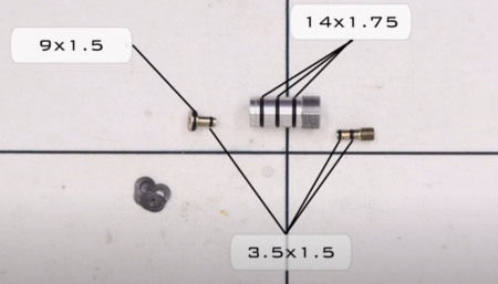
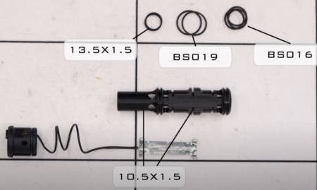
O rings used in Delta Wolf
| Delta Wolf | Size | IMP or Metric | Shure | LOC | |
|---|---|---|---|---|---|
| 2 | 13 x 15 | M | N70 | ||
| 1 | 14.5 x 3 | M | N90 | ||
| 1 | 004 | IMP | N90 | ||
| 2 | M12 | M | Bonded washer | ||
| 3 | 1/8 | BSP | Bonded washer | ||
| 4 | 15 x 2 | M | N70 | ||
| 1 | 10 x 15 | M | N70 | ||
| 2 | 006 | IMP | N70 | ||
| 9 | 617 | IMP | N70 | ||
| 1 | 007 | IMP | N90 | ||
| 1 | 93 x 24 | M | N90 | ||
| 1 | 17 x 1.5 | M | N70 | ||
| 2 | 813 | IMP | N70 | ||
| 1 | 4 x 15 | M | N70 | ||
| 1 | 4.1 x 1.6 | M | N70 | .177 | |
| 1 | 009 | IMP | N70 | .22 | |
| 1 | 6.1 x 1.6 | M | N70 | .25 | |
| 1 | 75 x 15 | M | N70 | .30 |
REGULATOR INSTALLATION
Under normal conditions the regulator should not be dismantled. Tolerances and cleanliness are extremely critical in regulator assembly and user servicing of a regulator should only be attempted where there are no other options.
1:18 Re-stack the Belville washers in pairs on the piston. The first pair are placed cup downwards facing the piston. The second pair face the opposite way. The final two pairs alternate.
Regulator stripped
1:52 Add a small amount of silicon grease to the ‘o’ rings on the piston.
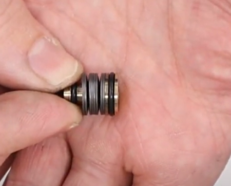
Correctly stacked and lubricated
2:08 Put the piston into the base of the regulator (non-threaded, recessed end).
2:14 Drop the small plastic sealing disc into the other end of the regulator body (threaded end). Make sure it is properly seated.
2:43 Apply a small amount silicon grease to the ‘o’ rings on the adjuster screw. Drop the adjuster screw into the regulator body on top of the sealing disc and screw it flush to the top of the regulator body using a flat bladed screwdriver.
3:08 Apply a small amount of silicon grease to the three ‘o’ rings on the regulator housing.
3:15 Push the regulator body into the lower of the two holes in the front of the main block. Then screw home using the Daystate regulator tool, screw it fully home. If you do not have access to the Daystate regulator tool you could use a pair of snap ring pliers.
Screw the regulator into the body
3:36 Screw in the adjuster screw using a flat bladed screwdriver until you feel it gently come up to a stop. Then back out a quarter of a turn. You will need to re-adjust the regulator pressure later.
A separate regulator strip and assembly video for the Regulator is available here
VALVE RE-BUILD AND INSTALLATION
4:08 Take the valve pin and apply a light coat of silicon grease to the ‘o’ ring.
4:14 Gently press the valve pin into the front half of the valve. Then drop the spring on top.
4:35 Take the back half of the valve and drop the spring guide to the hole. (4:39) The two parts of the valve are hooked together through the snap ring.
5:10 Apply a small amount of silicon grease to the three ‘o’ rings on the valve. (5:15) Take the block and insert the valve into the bottom hole in the rear of the block, taking care to orient the transfer port with the top of the block.
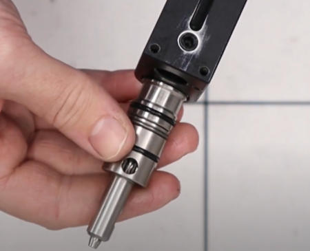
Valve orientation into the block
5:54 After applying a light coat of silicon grease, insert the two sealing ‘o’ rings over the valve. The smaller ‘o’ ring is fitted first followed by the larger ‘o’ ring. Use a plastic pick to ensure they are properly seated.
Correct ‘o’ ring installation on the valve
6:10 Drop the retaining nut over the valve and screw it in using the Daystate tool Daystate tool and 19mm spanner, or a set of snap ring pliers to tighten.
Using the Daystate valve tool to retighten
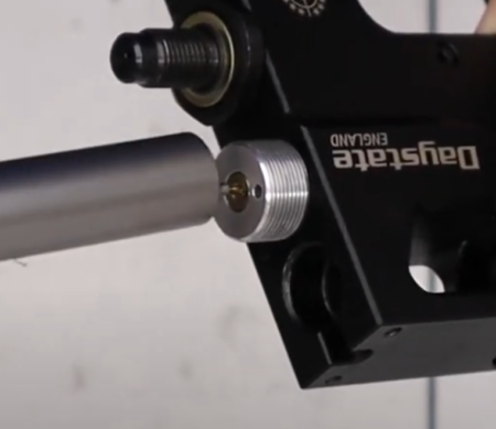
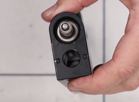
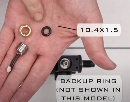
FILL PORT INSTALLATION
6:45 Apply a light coat of silicon grease to the urethane ‘o’ ring on the one way-valve and then install the valve into the threaded end of the fill valve housing with the ‘o’ ring uppermost.
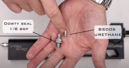
Filler port components
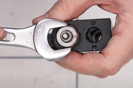
7:04 Turn the main block upside down and insert the filler valve into the front hole and tighten with a 10mm deep socket.
7:20 Apply a light coat of silicon grease to the fill gauge ‘o’ ring and drop into the hole on the side of the block immediately above the filler valve, making sure it is properly seated.
7:32 Screw the fill pressure gauge into the hole. Tighten with a 22mm spanner, but do not over-tighten. (7:53) Put the plastic collar over the top of the fill pressure gauge.
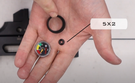
Pressure gauge
PRESSURE SENSOR INSTALLATION
Note: there are several different versions of the pressure sensor that have slightly different components. However, the process outlined below applies.
08:26 Apply a light coat of silicon grease to the ‘o’ ring and drop it into the hole on the underside of the block, making sure it is seated flat.
Pressure sensor
08:37 Drop the pressure sensor on top of the ‘o’ ring and secure by screwing in the brass nut which can be tightened first by hand and then by using a set of bent snap ring pliers.
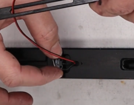
09:02 Attach the second half of the pressure sensor by carefully connecting the two plastic blocks. Older versions of the Delta Wolf may have a single wire rather than two wires connected together.
Pressure sensor wire is 1-piece on earlier rifles, the later 2-piece wire is shown
09:38 Pass the pressure sensor wire through the aperture in the block.
SAFTEY BAR INSTALLATION
10:13 Apply a light coat of moly grease to the two rotors.
10:21 Note there are several cut outs on the safety bar. Insert the bar into the hole on the left side of the block that has a second hole just above it.
Safety bar installation
10:35 Attach the safety switch on the opposite side using a 2mm allen key.
TRIGGER UNIT ASSEMBLY
11:11 Apply a light coat of moly grease to the base of the brass trigger shoe and the spring guide. Put the shoe into the spring.
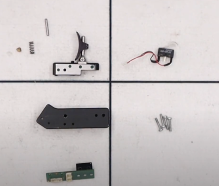
Trigger components
11:26 Put the spring into the trigger block using the hole immediately above the trigger blade.
11:32 Insert the trigger block into the trigger housing taking care to align the hole in the block with the second hole from the front in the trigger housing. This will enable you to insert the small pin (11:42).
11:50 Place the trigger electronic board into the top of the trigger housing and add the two securing screws (11:55) in two uppermost holes, tightening with a cross head screwdriver.
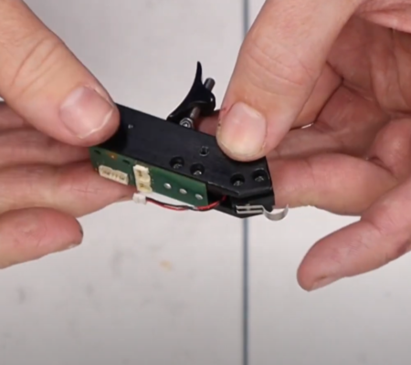
The complete trigger
12:05 Install the electronic safety switch sensor into the back of the trigger unit and secure with the remaining two screws into the rearmost holes using a crosshead screwdriver.
Inserting the trigger unit into the block
12:40 Connect the top mount connection to the electronic board with the cut outs facing down (12:57).
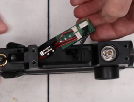
TRIGGER UNIT INSTALLATION
13:20 Take the main wiring loom and locate the connector that is attached to multiple individual wires. Insert into the large aperture at the front of the block at the top until it is visible at the top of the trigger portion of the block.
13:56 Feed the pressure sensor wire through the trigger block to connect to the electronic board. A set of tweezers is useful here.
14:33 Connect the wire from the main wiring loom to the electronic board.
15:00 Take the grey mounting piece to secure all the connections into the block and secure with two screws using a crosshead screwdriver.
15:50 Insert the assembled trigger block into the main block, gently pulling the main wiring loom from the top of the block to take up any slack. Secure the trigger block into the main block with four allen screws (two each side) using a 2mm allen key.
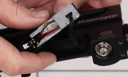
Grey mounting piece – caution do not trap the wires under the block
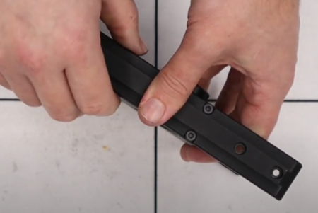
16:56 The bottom Picatinny accessory rail is attached using four allen screws and a 3mm allen key.
17:33 Reattach the magnet fill valve cover.
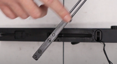
TOP RAIL AND COCKING LEVER INSTALLATION
17:39 Take the Delrin spacer and drop into the oval hole in the bottom of the block forward of the slot with the long side facing the top so the wires will feed through the cut out.
Delrin spacer orientation
18:04 Add a light coat of moly grease or lithium grease to the mating surfaces on the bottom of the block.
18:24 Apply a light coat of moly grease to the cocking linkage.
Lightly lube the linkage
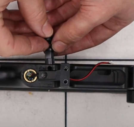
18:58 Poke the connector section of the cocking sensor through the underside of the slot in the cocking linkage so it emerges on the flat side of the linkage.
19:14 Attach the cocking sensor switch to the two nubs on the bottom of the main block.
Attaching the cocking sensor
19:29 The cocking rail can then be located onto the bottom of the main block and secured with the aluminium channel (19:36).
19:50 A dab of moly grease will help keep the spacers in place while you locate the channel. (20:20) Feed the cocking sensor through the small slot in the middle of the channel and then place the flat side of the channel on top of the spacers and secure using the screws and a flat head screwdriver. (20:50) Check the cocking linkage slides freely.
20:58 Locate the main wire into the channel and connect the cocking sensor to the last but one connection on the main wire (21:13). Note that in the factory, the wires are held into the channel with a small amount of hot glue. If necessary, you can reapply some hot glue to keep the wires in place.
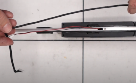
Feeding the wire into the channel
22:03 Add a small amount of moly grease to the central channel in the underside of the top rail.
22:23 As you reattach the top rail, take care to not pinch any of the wires in the main block.
Attach the top rail taking care not to trap any wires
22:56 Orient the top rail so the two holes are at the front and place on the main block. Secure with the six screws. The longer screws are inserted into the middle of the top rail to also connect the cocking arm (do not insert at this point), and the shorter screws go at the front above the pressure gauge, and at the back of the main block. Use a 3mm allen key.
24:20 You will need to decide which side of the main block you will want to install the cocking arm.
24:33 Take the cocking arm and add a small amount of moly grease to the pivot point.
24:46 Insert the brass bush into the front pivot hole having first applied a small amount of moly grease.
24:59 Locate the three holes in the rear of the cocking linkage visible in the slot at the top of the main block. The outer holes line up with two pins in the cocking arm. The centre hole accepts a screw through the open slot which is tightened with a flat headed screwdriver.
25:45 Rotate the cocking arm so the front hole aligns with the hole at the top of the main block and secure with one of the two longer screws used to connect the top rail to the main block. Tighten with a 3mm allen key.
26:01 Install the cover plate to the opposite side, locating the notched end first facing the rear of the block.
26:19 Insert the remaining screw into the top of the block and tighten with a 3mm allen key.
26:27 The drop-down handle is attached using a 2.5mm allen key to tighten the securing bolt.
FRONT BLOCK INSTALLATION
26:55 Connect the two connector blocks on the front block and on the front of the main block.
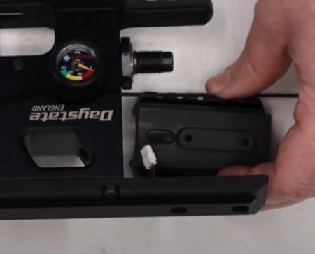
Connect the two connector blocks on the front block
27:15 Fold the wire and connecting blocks into the top rail to the top block so that it mates snugly with the top rail.
27:38 Insert the two screws and tighten with a 3mm allen key to secure the top block.
ELECTRONIC HOUSING REBUILD
28:03 Insert the electronic board into the rear block and (28:20) attach the connector block to the block in the front of the board.
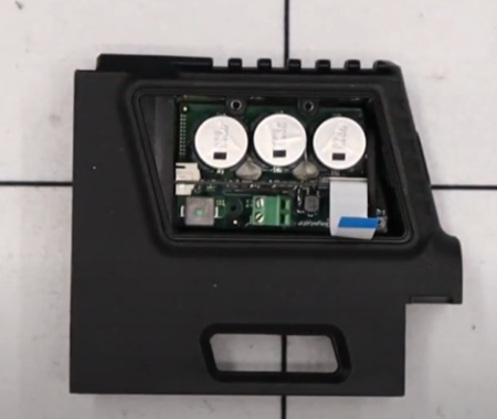
Board installed
28:35 Locate the electronic board into the cavity at the rear of the block taking care to not trap the wire underneath.
29:07 Drop the two spacers rings into the large hole at the back of the block. Note that newer rifles may have one larger spacer ring.
29:27 Install the coil into the coil housing and drop into the large hole at the back of the block on top of the spacer rings with the red wire orientated towards the electronic board so that it aligns with the connections on the green block.
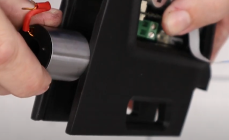
Installing the coil
30:00 Take the plastic hammer housing and drop into the hole over the coil housing ensuring the slot in the hammer housing is aligned with the coil wire.
30:17 Drop the hammer through the hammer housing. Drop the plastic locking component over the top aligning the tabs and then rotate using a part of snap ring pliers to lock clockwise into place.
30:52 Secure the electronic board into the housing using the two screws and insulating washers. Tighten with a T6 torx bit.
31:31 Connect the coil wires into the terminals using a flat head screwdriver to tighten the screws.
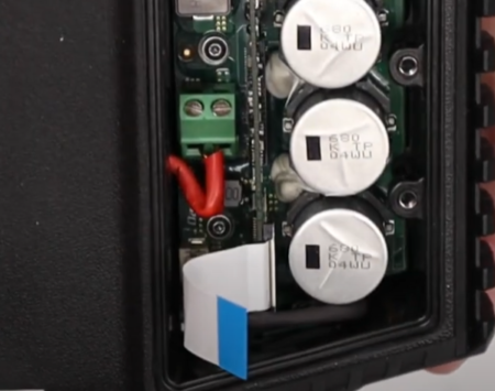
Coil terminals do not overtighten
32:06 Ensure the grey connection tabs on the screen are pushed down to accept the ribbon. (32:19) Pass the ribbon under the white connector bar and secure by pushing up the two grey tabs to lock the ribbon cable into position.
32:43 Locate the screen on top of the electronic board cavity and secure with two allen screws and a 2mm allen key.
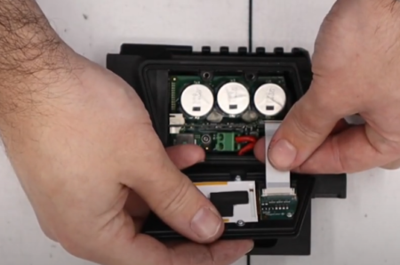
Connecting the screen
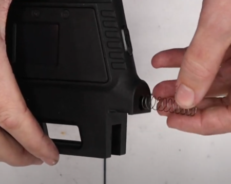
33:16 To install the battery cover latch first install the spring into the hole at the rear of the butt section. A pair of tweezers will help you position the spring correctly. (33:27) Insert the catch on top of the spring ensuring the angled end is pointed to the back of the rifle. (33:44) Secure with the screw that has a red spacer using a 2mm allen key.
34:14 The hammer return spring is inserted into the hole at the front of the electronic block.
Hammer spring
ELECTRONIC HOUSING INSTALLATION
34:30 Ensure the electronic connection in the top rail is tucked away so it does not get pinched.
34:54 Align the main block with the rear electronic block and push together. (35:17) Insert the four securing screws at the top of the top rail and tighten with a 3mm allen key.
Rear block replacement
35:43 Insert the grub screw into the hole just below the breech using a 3mm allen key.
35:59 Connect the connector on the wire at the rear of the electronic block into the uppermost of two sockets. (36:23) Locate the main wire into the channel in the securing nut.
36:33 Insert the cap using a 3mm allen key.
36:45 The Picatinny inter rail is attached by sliding it over the top rail dovetail and securing the four screws using a 3mm allen key.
37:02 The cheek piece slides onto the dovetail rail at the rear of the rifle, oriented for either left or right hand shooters, and secured with two screws using a 2.5mm allen key.
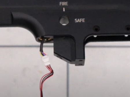
37:28 Add a small amount of moly grease to the safety pin and drop into the hole located in left of the underside of the main block under the safety switch pointed end first. Locate the safety switch to either ‘fire’ or ‘safe’.
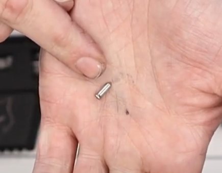
Safety pin goes in point first
37:50 Take the safety spring and apply a small amount of moly grease and drop into the smaller of the two holes in the underside of the grip. (38:05) Offer the pistol grip up with the spring over the safety pin. The grip is then secured through the base with a screw and washer tightened with a 5mm allen key.
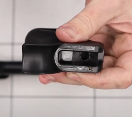
Add the safety spring
CHRONOGRAPH AND SHROUD ASSEMBLY
39:30 Hook the two ‘o’ rings over the chronograph and pull down over the wire. (39:44) Hook one of the larger ‘o’ rings over the chronograph and pull this over the wire as well.
Chronograph assembly
39:50 Install the chronograph onto the housing. You do not need to apply silicon grease to any of the ‘o’ rings associated with the chronograph.
40:10 Apply the ‘o’ ring over the end of the circuit board and housing. Then feed the larger of the three ‘o’ rings through which the wire runs and secure it on the housing at the back of the circuit board to hold the wire in place.
40:26 Install the three ‘o’ rings over the housing to secure the circuit board in place.
40:59 Slide the remaining two ‘o’ rings on the wire over the aluminium housing. Older models may have a Delrin housing.
41:23 Slide the barrel through the back boss, loop spare coils of wire around the barrel and screw into the end of the barrel into the chronograph housing. You can ensure the chronograph housing is firmly screwed in by putting the barrel into a soft jaw vice, then inserting a plastic bar through the holes at the back of the chronograph circuit board for leverage.
42:12 Pre-install the two securing grub screws into the back boss using a 2.5mm allen key. Tighten until they just touch the barrel then back off a quarter turn.
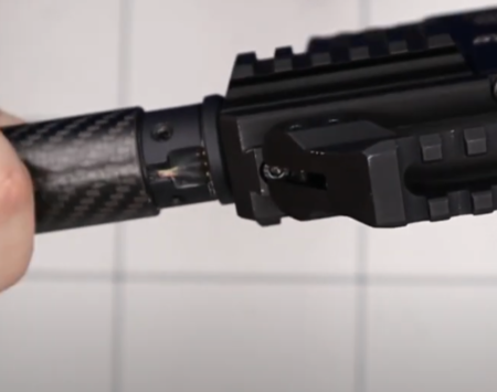
BARREL INSTALLATION
42:50 Insert the back of the barrel into the upper hole in the front of the main block and pass it through the main block. (43:09) Ensure the dimple in the barrel is aligned with the hole forward of the breech. Insert the grub screw and tighten with a 3mm allen key.
Barrel orientation
43:26 Align the shroud boss so the pogo connection connects with the terminal at the front of the main block. Tighten the boss retaining grub screws ensuring it is fractionally forward of the main block.
44:08 Roll one of the ‘o’ rings on the back of the chronograph housing to capture the excess chronograph wire.
44:18 Take the carbon shroud and locate the two retaining holes at the rear and ensuring they are facing the bottom of the rifle, slide the shroud over the barrel. Ensuring no wires are pinched, push the shroud over the boss. (44:45) Secure the shroud by inserting the two grub screws and tightening with a 2.5mm allen key.
Shroud installation
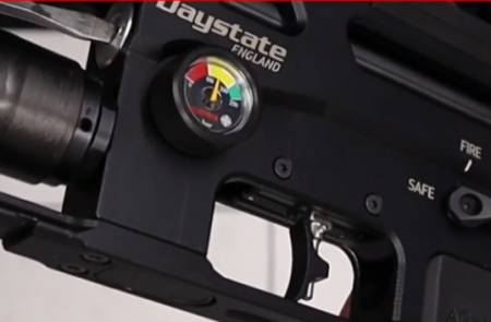
RESETTNG THE REGULATOR
Note: With air in the rifle, the regulator adjuster cannot be adjusted in the clockwise direction as this will result in damage.
47:25 The regulator is adjusted via the adjuster screw in the front of the regulator above the air bottle using a flat bladed screwdriver.
The regulator adjusts anti-clockwise only
47:48 Increasing the regulator pressure is achieved by turning the adjuster screw anti clockwise. Reducing regulator pressure is achieved by turning the screw clockwise. However, this should not be done when the rifle is fully pressurised as this can result in damage if the regulator contains more than 40 BAR. On sub 12 ft/lbs an anti-tamper sticker is used to demonstrate the regulator has not been adjusted away from factory settings.
Once the regulator pressure has been set. Use the chronograph to ensure the rifle is set at a level appropriate to local laws.
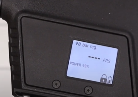
The active regulator pressure is shown on the display screen
INSTALLING THE BOTTLE VALVE
- Test screw in the valve into the bottle, then remove
- Clean off any metal swarth on the valve assembly and inside the bottle as this will cause leaks
- Apply engineering adhesive – nut grade- and grease on the oring. (be careful not to get the adhesive on the oring)
- Screw in the valve to 30 nm torque with the tool available from best fittings
- https://www.bestfittings.co.uk/shop/fill-probes-adaptors/buddy-bottles-valves/fx-buddy-bottle-valve-installation-removal-tool/
- leave to dry for 12 hours
- Attach to the rifle and fill checking for leaks