THE BLACKWOLF
Disassembly Guide


INTRODUCTION
Daystate air rifles are engineered to the highest standards, but like anything else, they require repairs and servicing work to be carried out both in and out of warranty.
The aim of this guide and the accompanying video is to provide instruction on how to disassemble the Daystate Blackwolf.
In addition, a separate regulator service video is available here, for a cylinder or bottle switch we have made a separate video which can be viewed here. fitting a carbon tensioner view here, Trigger Adjustment video here Volumax fitment (TAC version only) here
Compressed air is dangerous. You should only use this guide if you are a qualified and experienced gunsmith used to working with compressed air. Before you carry out any work on the Daystate Wolverine, or any PCP air rifle for that matter, you must ensure it is not cocked, not loaded and empty of air.
HISTORY
The development of modular rifle systems in Delta Wolf and BRK Ghost revealed a need for modular full length mechanical Daystate rifle. The Blackwolf was to be this rifle. Launched in March 2025, though some prototypes had been revealed the previous year at the EBR match. The launch versions of Blackwolf included three wooden stocks and one TAC version with a synthetic aluminium target stock. In addition different bottle and cylinder lengths were offered at launch as well as the rifle being available in four calibres and three different barrel lengths. it shares much of the thinking and some components from the BRK Ghost but in a full length non-bullpup design.


TOOLS YOU WILL NEED
- Allen keys: 2mm; 2.5mm; 3mm; 4mm; 5mm
- T10 TORX bit (up to July 2025 assembly)
- 10mm Deep socket
- Daystate Regulator removal tool
- Daystate Valve removal tool
- 16mm thin open-end spanner
- 22mm open-end spanner
- Tweezers
- 3-pin M5 A/T removal tool (large)- available from Daystate part number DANTITOOLXX
- Digital callipers
- O-rings used in Blackwolf
- O-ring pick
BLACKWOLF O-RING LIST
| PART NUMB. | QTY | SIZE | IMP or METRIC | SHURE | LOCATION |
|---|---|---|---|---|---|
| 4 | 2 | 14.5x1.5 | M | 70 | Breech/barrel |
| 5 | 1 | 118 | IMP | 70 | Housing b |
| 6 | 3 | 014 | IMP | 70 | valve housing |
| 11 | 1 | 007 | IMP | Urethane | valve |
| 80 | 1 | 28x1.78 | M | 70 | Barrel .22 |
| 80 | 1 | 1x1.6 | M | 70 | Barrel .177 |
| 80 | 1 | 5x1.5 | M | 70 | Barrel .30 |
| 80 | 1 | 1x1.6 | M | 70 | Barrel .25 |
| 85 | 1 | 019 | IMP | 70 | Shroud |
| 91 | 2 | 3.5x2.62 | M | 70 | gauge |
| 91 | 2 | 3.5x2.62 | M | 70 | gauge |
| 91 | 2 | 3.6x2.5 | M | 70 | gauge |
| 91 | 2 | 5x2 | M | 70 | gauge |
| 96 | 1 | 006 | IMP | Urethane | filler |
| 103 | 1 | 617 | IMP | 70 | bottle |
| 107 | 4 | 122 | IMP | 70 |
REMOVING THE STOCK AND DE-GASSING
Removing the stock will make it easier to work on the rifle and prevent any damage to it. You will need to remove all the air (de-gas in the video) to work safely on the rifle.
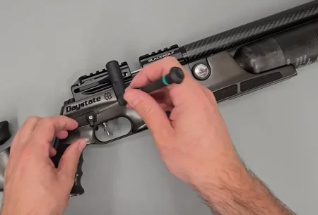
Remove the safety catches
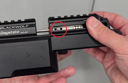
01:34 Remove the safety catches of both sides of the rifle using a 2mm allen key (T10 TORX up to July 2025). Ensure the spacer on each side is also removed and retained.
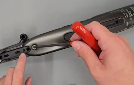
Stock bolt removal
01:54 Remove the M8 stock bolt using a 5mm Allen key.
Removing air from the rifle
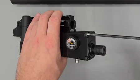
02:27 Using a deep 10mm socket loosen the foster fitting by one or two turns allowing to allow air to leak out of the rifle.
Check both gauges read zero air. If necessary, fire the rifle until the regulator gauge of the left side is empty.
REMOVING THE SHROUD AND BARREL
Removing the barrel will give you access to the breech seal ‘o’ ring and to two other ‘o’ rings inside the breech block that seal the transfer port.
Removing the scroud
5:15 unscrew and remove the shroud.
Removing the internal scroud support
6:05 using a 16mm thin spanner unscrew the front shroud support. Note: this part needs removing to install the carbon fibre tensioner. If a tensioner is already factory-fitted e.g. Walnut, Laminate or TAC stock versions, the tensioner is bonded in place and we do not recommend its removal.
The barrel can also be removed wit the shroud in place
6:36 loosen the two 3mm Allen screws on top of the barrel. Remove the barrel. Note the position of the two barrel-sealing o-rings (4) and the barrel internal oring (80).
Barrel oring positions
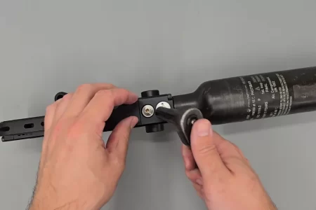
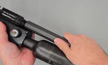
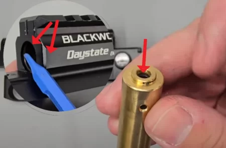
REMOVE AIR BOTTLE OR AIR CYLINDER
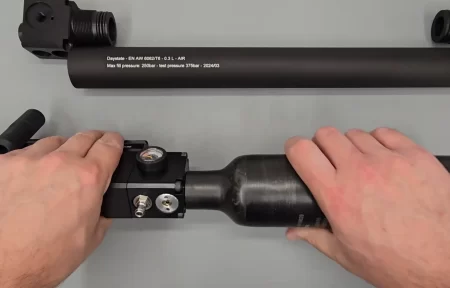
Unscrewing bottle or cylinder
08:47 Unscrew bottle or Cylinder off the housing.
Removing the bottle housing
10:07 Unscrew the 4 M4 Allen bolts holding the housing B (bottle or housing C (cylinder) from the main body and remove.
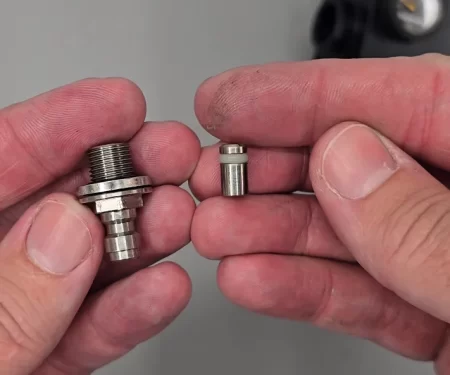
Foster fitting componants note the urethane seal
11:33 remove the foster fitting note because of the filter in the front of the unit it is necessary to apply a small amount of air pressure to push the seal out of the foster fitting.
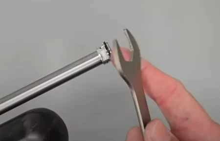
REGULATOR AND GAUGE REMOVAL
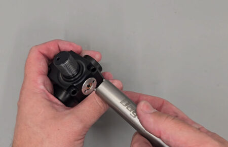
Regulator can be unscrewed with the housing still in the rifle
12:51 using the daystate regulator removal tool, or a circlip spanner, remove the regulator from its housing.
Remove the covers on the gauges and using a 22mm spanner the two gauges can be removed. Note the O-ring underneath is individually sized to help with alignment of the gauge, so these should not be mixed up and should a replacement be needed, the existing O-ring should be measured.
The Huma-Air regulator fitted to Blackwolf is identical to the unit fitted to the BRK Ghost. A full regulator service video is available here
REMOVING THE VALVE

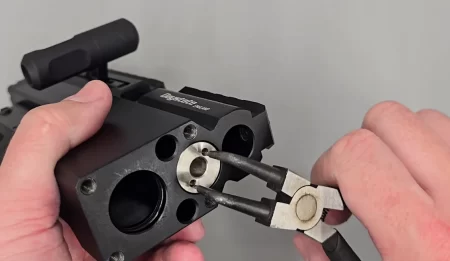
Valve removal
19:12 using a Daystate valve removal tool or as shown here a stout pair of circlip plyers, remove the firing valve cap allowing access to the valve spring and valve itself.

Valve body retaining screw
19:44 Using a 2.5mm Allen screw loosen the valve body retaining screw in the magazine well.
20:11 tap out the valve seal and valve body note: the 12 ft/lbs valve is two-piece and the High Power valve is one piece.

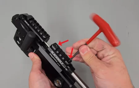
REMOVING THE COCKING ARM AND PELLET PROBE
Cover plate and cocoking arm screws
26:49 Remove the cover plate screw (1) using a 3mm Allen key. The cover plate can be slid out.
Removing the side lever securing screw
27:20 Remove the side lever securing screw (2.5mm) and remove the cocking arm securing screw (2) – be aware that some rifles may contain a fine shim at this point – to remove the cocking arm. 28:10
HAMMER REMOVAL
Access to the hammer, hammer spring and power adjuster
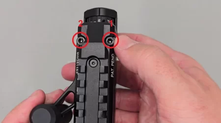
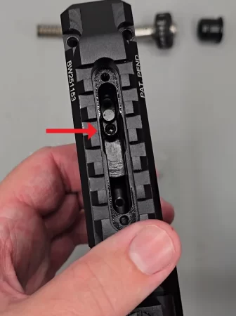
28:33 remove the 2 safety catch securing screws. For sub 12 ft/lbs rifles one will be of the anti-tamper type the other (or both in the case of high-power rifles) will be 3mm.
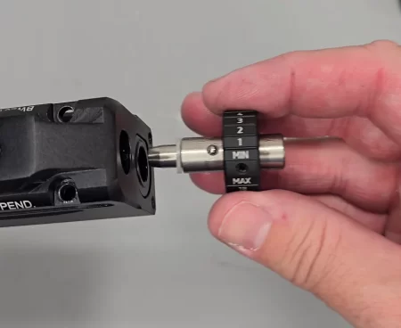
Power adjuster removal
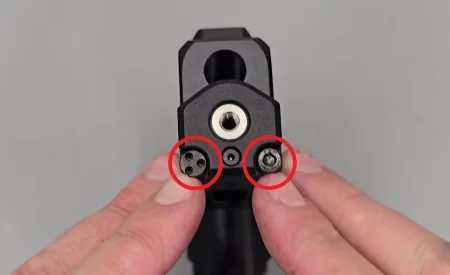
29:09 remove the power adjuster assembly. Remove the hammer plug, remove the hammer spring.
30:08 With a 2mm Allen key, remove the breech bolt cover plate.
Location of the cocking-dog screw
30: 23 remove the cocking dog using a 2mm Allen key to loosen the 2 screws. Tip the action back to slide out the hammer and cocking dog.