THE AIR WOLF
Disassembly Guide
ON THIS PAGE
- Tools you will need
- Notes on Air Wolf
- Removing the stock and disconnecting the battery
- De-gassing the rifle and removing the fill port
- Removing and disassembling the shroud
- Removing the bottle and bottle housing
- Removing the valve and valve seat
- Additional bottle and bottle housing information
- Removing the breechblock
- Removing the LCD screen
- Removing the barrel
- Removing the pellet probe
- Removing the trigger housing and main board
- Disassembling the hammer housing and removing the coil
- Disassembling the safety
- Removing the main circuit board
- Disassembling the trigger
AIR WOLF PARTS LIST
| PART NUMB. | DESCRIPTION | CODE | Q.TY |
|---|---|---|---|
| 1 | breech block elec. ( engraved air wolf ) | D3BKMACHDBT | 1 |
| 2 | alum. breech insert 0.177" | D3ALINS17BT | 1 |
| 2 | alum. breech insert 0.20" | D3ALINS20BT | 1 |
| 2 | alum. breech insert 0.22" | D3ALINS22BT | 1 |
| 2 | alum. breech insert 0.25" | D3ALINS25BT | 1 |
| 3 | Dowel Ø1/8 x 1'' | D3DOW18X1X | 1 |
| 4 | Spring LC016A 10MW | D3SPR16A10M | 1 |
| 5 | skt set_UNI5929_M4x6 | D3SKTM4X6CO | 3 |
| 6 | skt set_UNI5929_M4x4 | D3SKTM4X4CO | 5 |
| 7 | BallBearing 1/8" (3.2) | D3BAL1800SC | 2 |
| 8 | Spring LC014A 6MW | LC014A 6MW | 2 |
| 9 | breech bolt 0,177" | D3BRBOL17BT | 1 |
| 9 | breech bolt 0,20" | D3BRBOL20BT | 1 |
| 9 | breech bolt 0,22" | D3BRBOL22BT | 1 |
| 9 | breech bolt 0,25" | D3BRBOL25BT | 1 |
| 10 | o ring 003 -NBR-70Sh ( cal. 0,177" ) | D3OR70003CO | 1 |
| 10 | o ring 005 -NBR-70Sh ( cal. 0,20" ) | D3OR70005CO | 1 |
| 10 | o ring 004 -NBR-70Sh ( cal. 0,22" ) | D3OR70004CO | 1 |
| 10 | o ring 005 -NBR-70Sh ( cal. 0,25" ) | D3OR70005CO | 1 |
| 11 | Breech bolt handle RH | D3BOLTHANBR | 1 |
| 11 | Breech bolt handle LH | MISSING | 1 |
| 12 | magazine activator RH | D3MAGACTVXX | 1 |
| 12 | magazine activator LH | D3MAGCTLH | 1 |
| 13 | anti tamper screw 4- BA x 3/4" | D3TAMSCREXX | 2 |
| 14 | slt csk 4BA x 1/2" | D3CSK4BAX12 | 2 |
| 15 | skt cap_UNI5931_M3x20 | D3SKTM320CO | 2 |
| 16 | port bush Ø3,0 | D3PORBUS3.0 | 1 |
| 16 | port bush Ø3,2 | D3PORBUS3.2 | 1 |
| 16 | port bush Ø3,4 | D3PORBUS3.4 | 1 |
| 16 | port bush Ø3,5 | D3PORBUS3.5 | 1 |
| 16 | port bush Ø4,2 | D3PORBUS4.2 | 1 |
| 16 | port bush Ø4,8 | D3PORBUS4.8 | 1 |
| 17 | o ring 008 ( Ø4.47x1.78 ) -NBR-90Sh | BOR00890SH | 2 |
| 18 | Bolt Spacer ( short ) | MISSING | 1 |
| 19 | Skt Cap 4BAx1/4" | MISSING | 1 |
| 20 | WP disc | DETICHETTEX | 1 |
| 21 | bezel display ( glued with LCD display in UK ) | D3BEZEL00BT | 1 |
| 22 | LCD display - wired FFC | 1 | |
| 23 | slt chead zinc - UNI6107 - M2x10 | D3CHEM210CO | 2 |
| 24 | barrel 17" - cal 0.177 | D3BAR1717BT | 1 |
| 24 | barrel 17" - cal 0.20 | D3BAR2017BT | 1 |
| 24 | barrel 17" - cal 0.22 | D3BAR2217BT | 1 |
| 24 | barrel 17" - cal 0.25 | D3BAR2517BT | 1 |
| 25 | striker housing AW | D3MAIBOAWXX | 1 |
| 26 | trigger housing | D3TRHOUELTH | 1 |
| 27 | trigger blade electrical | D3BLADELCTB | 1 |
| 28 | circuit board | MISSING | 1 |
| 29 | skt set - UNI5923 - M3x12 | D3SKTFM312CO | 1 |
| 30 | skt set - UNI5923 - M3x4 | D3SCKM3X4CO | 1 |
| 31 | skt set - UNI5923 - M3x6 | DSCKM3XM6CO | 2 |
| 32 | brass spring guide | D3BRASTRIGUI | 1 |
| 33 | elec. trigger spring LCO014B | D3SPR14B2CO | 1 |
| 34 | trigger leaf spring | D3LEAFSPRTH | 1 |
| 35 | dowel - ISO2338 - Ø2x14 | D3DOW02X14X | 1 |
| 36 | slt chead zinc - UNI6107 - M4x6 | 1 | |
| 37 | microswitch_D2F-L - wired | D3BPBREMISW | 1 |
| 38 | slt chead zinc - UNI6107 - M2x12 | 2 | |
| 39 | nut - DIN934 - M2 | D3NUT2MMOCO | 2 |
| 40 | female recharge bush - wired | 1 | |
| 41 | safety lock switch - wired | 1 | |
| 42 | slt chead zinc - UNI6107 - M3x6 | 3 | |
| 43 | Skt Cap 1/4-BSW x 3/4" | 1 | |
| 44 | sticky spots - large ( 140x38 mm ) | 1 | |
| 45 | circuit board - CDT | 1 | |
| 46 | sticky spots - small ( 60x22 mm / cut ) | 1 | |
| 47 | solenoid plastic spacer | 2 | |
| 48 | solenoid | 1 | |
| 49 | solenoid striker hammer | D3SOSTHAMXX | 1 |
| 50 | solenoid alum. spacer | D3ALSP110XX | 1 |
| 51 | solenoid spring | D3SOLSPRICD | 1 |
| 52 | o-ring 118 - Ø21.89x2.62 (3057) - NBR-70Sh | D3ORI118N70 | 1 |
| 53 | Safety Body | D3SABODELSC | 1 |
| 54 | grub screw cup point 4BA x 1/8" | D3SKT4A18SC | 3 |
| 55 | skt cap_UNI5931_M6x6 | D3CAPM6X6XX | 1 |
| 56 | dowel_ISO8734_Ø2.5x8 | D3DOW25X8XX | 1 |
| 57 | Safety Cover UNI | D3REARCAPSC | 1 |
| 58 | Skt Cap 4BAx1/2" | D3SKT4B12CO | 1 |
| 59 | nut 4 BA | D3NUT4BAXXX | 1 |
| 60 | Rubber shock absorber ( short ) | D3BUN11X7CO | 1 |
| 60 | Rubber shock absorber ( long - FAC ) | D3BUN11X11X | 1 |
| 61 | Perspex Safety Catch Lever | D3CLEARLESC | 1 |
| 62 | HOUSING A 12-30 fpe | D3HSA1230HA | 1 |
| 62 | HOUSING A 40-60 fpe | D3HSAAW1840 | 1 |
| 63 | o-ring 006 - Ø2.9x1.78 (2012) - NBR - 70Sh | D3ORN7006CO | 1 |
| 64 | Striker Valve O'ring Retainer | D3STRVORRCO | 1 |
| 65 | valve stem | D3STEMHARPXX | 1 |
| 66 | valve seal Ø4.5 ( ???? Check !! ) | D3HARSEAL12 | 1 |
| 66 | valve seal Ø5.0 ( ???? Check !! ) | D3HARSEAR12 | 1 |
| 66 | valve seal Ø5.3 ( cal. 0,25 - 40Ft/Lbs ) | D3HARSEARFA | 1 |
| 67 | o-ring 111 - Ø10.77x2.62 (3043) urethane | D3ORN9111CO | 1 |
| 68 | Stem spring | D3SPR3513CO | 1 |
| 69 | HOUSING B - AW | D3HSBWOLHA | 1 |
| 70 | o-ring 112 ( Ø12.37x2.62 ) - NBR 70SH | D3OR11200CO | 2 or 1 |
| 70* | o-ring 014 (Ø12.42x1.78)-NBR-70Sh ( ISM without baffle ) | D3ORN7014CO | 1 or 0 |
| 71 | skt set - UNI5923 - M5x5 | D3SKTM5X5CO | 1 |
| 72 | skt cap_UNI5931_M5x25 | D3SKTCM5X25 | 5 |
| 73 | air filter 1/8" | D3FILTRHUMK | 1 |
| 74 | dowty seal self centering 1/8 bsp | D3DOWSE18CO | 2 |
| 75 | Male Connector Extension | D3MALEEXTCO | 1 |
| 76 | o-ring 113 (3056) NBR | D3OR11300CO | 1 |
| 77 | stainless steel piston | D3PISTON00FV | 1 |
| 78 | o-ring 006 - Ø2.9x1.78 (2012) - urethane | D3ORURA06FV | 1 |
| 79 | male connector | D3MALECONCO | 1 |
| 80 | dowty seal self-centering M8 | D3DOWPP213CO | 1 |
| 81 | pressur sensor - wired | D3PRESSENCY | 1 |
| 82 | Skt Csk 2-BA x 3/8" | MISSING | 2 |
| 83 | Dowel Ø1/4"x 1.1/4'' | MISSING | 1 |
| 84 | o ring 617 ( Ø17.86x2.62 ) -NBR - 70Sh | D3OR70617MV | 1 |
| 85 | Bottle 500cc | D3BOTTLE500 | 1 |
| 86 | AIRWOLF - stock | MISSING | 1 |
| 87 | butt - pad | D3PADBLCUXXX | 1 |
| 88 | butt pad screw | D3SCRPAD5X35 | 2 |
| 89 | button head screw M12x35 | MISSING | 1 |
| 90 | dust cover | D3DUSTCARAW | 1 |
| 91 | Shroud AW-AR | D3ISMODAWAR | 1 |
| 92 | BREECH END INSERT | D3ISMINARAW | 1 |
| 93 | END CAP ADAPTOR ( with thread 1/2 unf ) | D3ADA12AWAR | 1 |
| 93 | END CAP ( without thread 1/2 unf , end cover not needed ) | D3ISMECARAW | 1 |
| 94 | KNURLED END COVER | D3KNURLAWAR | 1 or 0 |
| 95 | FAC BAFFLE | D3ISBAFARAW | 1 or 0 |
| 96 | MUZZEL END INSERT | D3ISMUZARAW | 1 |
| 97 | skt set tip - UNI5927 - M4x4 | D3SKTM4X4CO | 2 |
| 98 | o-ring 016 ( Ø15.6x1.78) - NBR - 70Sh | OR016N70 | 1 |
| 99 | battery type 1 | 1 | |
| 100 | battery type 2 | 1 |
INTRODUCTION
Daystate air rifles are engineered to the highest standards, but like anything else, they require repairs and servicing work to be carried out both in and out of warranty.
The aim of this guide and the accompanying video is to help you undertake work on the Daystate Air Wolf to address common faults.
Compressed air is dangerous. You should only use this guide if you are a qualified and experienced gunsmith used to working with compressed air. Before you carry out any work on the Daystate Air Wolf, or any PCP air rifle for that matter, you must ensure it is not cocked, not loaded and empty of air.
TOOLS YOU WILL NEED (00:33)
- Allen keys: 1.5mm, 2mm, 2.5mm, 3mm, 4mm, 5mm. 1/16, 3/32, 5/16 inch
- Long nose pliers
- 16 mm spanner
- Adjustable spanner
- Triangular anti-tamper tool
- Tweezers
- Flat blade screwdriver: 3mm, 6mm, 12mm
- Magnets
NOTES ON AIR WOLF
Approximately 11,000 Air Wolfs were made between 2005 and 2012 There are 3 distinct types of air wolf which can be easily distinguished by the seral number prefix:
AW- 2005- 2009 original Air Wolf with a CDT system.
MCT- 2009-2012 (model used in this strip down) improved consistency with MCT system.
MVT- 2018-2012 As the MCT but with the addition of a chronograph unit fitted inside the shroud replacing the front baffle.
The strip down procedure is virtually identical for all types with minor adaptions. MVT owners should tale care with the wire to the chronograph which is easily damaged. Should this happen, spares can be obtained from Daystate Ltd or their agents.
REMOVING THE STOCK AND DISCONNECTING THE BATTERY
01:10 Loosen and remove the stock bolt on the underside of the forend using a 5/16 allen key and the filler cap (01:18). This will allow the stock to lift off.
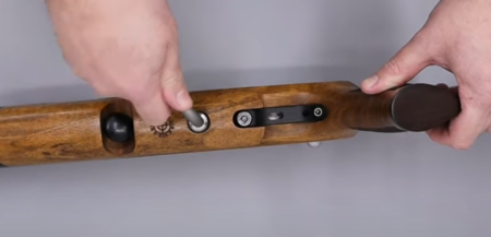
Stock removal uses an 8mm allen key
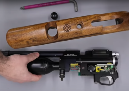
Stock removed
01:39 Remove the battery by disconnecting the plastic connector. Take care to pull on the plastic connector itself and not on the wires. It is recommended that once disconnected, you leave the rifle overnight so the battery can fully discharge.
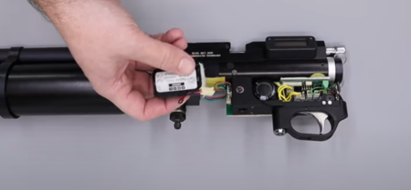
Battery location and removal
DE-GASSING THE RIFLE AND REMOVING THE FILL PORT
Note: The Daystate Air Wolf featured in the video is fitted with a fill port that does not have a gauze filter. As a result, it can be de-gassed using the Daystate degassing tool available for the Daystate website here or can be ordered from your local Daystate dealer. If your rifle has a fill port that is fitted with a gauze filter, the tool cannot be used. Details on how to de-gas without the de-gassing tool are provided later in the guide.
04:50 Disconnect the fitting from the bottom of the de-gassing tool and locate over the foster fit fill port and then screw in the de-gassing tool. You will feel air being dumped. Leave the tool in place until all air has been released. Then remove the tool.
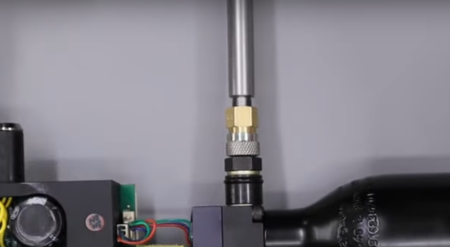
Bleed tool in use
05:19 Loosen the foster fit using a 16mm spanner to ensure all air has been released. If the foster fitting is not loose, it is likely that air is still in the bottle. Use the de-gassing tool again.
05:45 If your rifle is fitted with a gauze filter, use a 16mm spanner to loosen the foster fitting slowly to release the air. Check the foster fitting is completely loose to ensure all air has been released.
06:12 The foster fitting can now be unscrewed and removed.
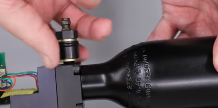
Removing the complete filler valve assembly
06:18 The two components to the foster fitting can be separated by placing the rounder end in a soft jaw vice and loosening the other end with a 16mm spanner.
06:48 The one-way fill valve is removed by placing an allen key or similar into the foster fitting and pushing it out.
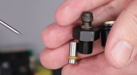
Filling valve dismantled
REMOVING AND DISASSEMBLING THE SHROUD
07:19 The barrel band is removed by loosening the three securing grub screws using a 1.5mm allen key. This will allow the barrel band to slide off the bottle.
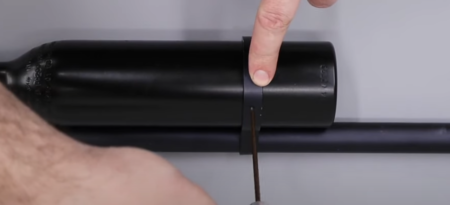
Later rifles have a barrel support
07:44 The shroud is removed by loosening the grub screws on the shroud above the neck of the air bottle using a 2mm allen key. This will allow the shroud to slide off the barrel.
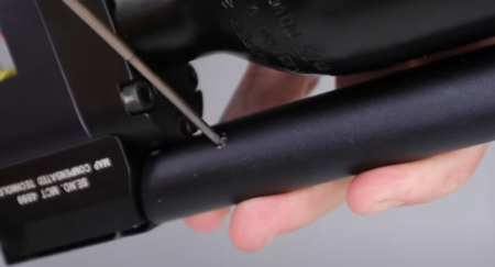
Two screws secure the shroud
08:08 Remove the thread protector from the muzzle end of the shroud.
08:16 Use a wide flat bladed screwdriver to remove the end cap from the muzzle end of the shroud.
08:32 Pull out the baffle. Take care as the baffle is likely to be covered in lead dust.
08:48 Use a nylon rod or similar and insert into the back of the shroud to push out the barrel carrier.
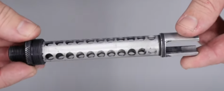
The complete barrel assembly
REMOVING THE BOTTLE AND BOTTLE HOUSING
09:18 The bottle can be unscrewed by hand.
09:30 On MCT and MVT models, disconnect the pressure sensor using a small set of long nose pliers. Pull the tab on the connector block back and use the pliers to grip the connector block and pull it free. Do not pull on the wires.
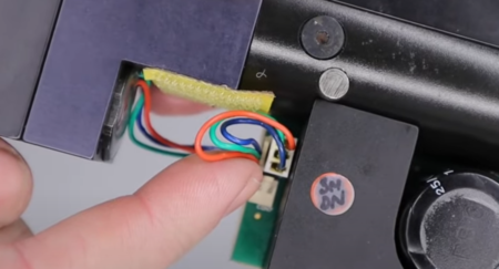
Pressure sensor plug
10:07 Loosen the five allen bolts on the bottle housing using a 4mm allen key. (10:25) Apply light pressure with your thumb to the bottle housing before removing the last screw as pressure from the valve return will push against the bottle housing.
10:40 With the bottle housing removed, feed the pressure sensor through the block so you can remove the housing itself.
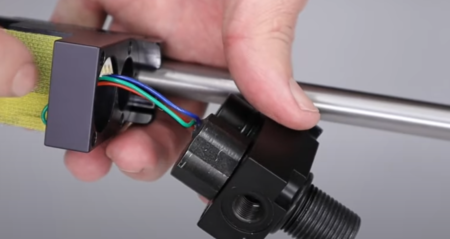
Removing the bottle housing
10:50 The pressure sensor is removed from the bottle using by using an adjustable spanner to loosen the sensor and then remove by hand.
REMOVING THE VALVE AND VALVE SEAT
11:46 The valve return spring, valve pin and valve seat are removed by pulling it free from the uppermost hole in the main block using a pair of tweezers.
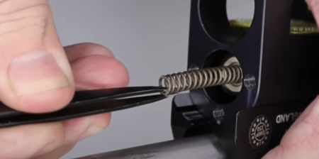
Valve, valve spring and valve seal removal
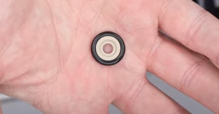
Valve seal shown face up, insert valve pin into this side
ADDITIONAL BOTTLE AND BOTTLE HOUSING INFORMATION
Note: Both the air bottle and bottle housing have a working life of 10 years. It is recommended they are both replaced after 10 years. The manufacture date of the bottle is stamped onto the bottle.
When replacing the bottle housing it is also recommended that you replace the five securing bolts. These are high tensile M5 x 27mm overall length including the head.
REMOVING THE BREECHBLOCK
14:21 To disconnect the screen, locate the connector at the top of the cavity. Push down on the two tabs with a flat head screwdriver. This will allow you to lift off the board (14:52) which is held in place with velcro.
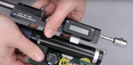
Separating the block from the tube
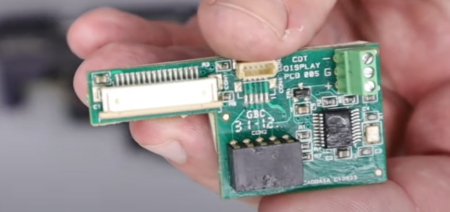
Display board showing tape connector top left
15:21 Remove the six screws on the top of the block. There are four cap head bolts and two flat head screws. Use a 2.5mm allen key to remove the four cap head bolts and a flat head bolts. Note that depending on the age and country of origin of your Air Wolf, the two rear-most bolts may not be allen bolts. They could be triangle anti-tamper bolts which will require the Daystate anti-tamper tool to remove. Pull back the bolt to undo the two flat head screws.
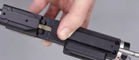
6 screws connect the block, front are 3mm, middle are slotted and rear are 3.32in
16:19 Pull the two halves of the block apart. Take care to not catch the ribbon cable in the screen cavity.
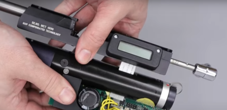
Separating the block from the tube
REMOVING THE LCD SCREEN
16:40 To remove the LCD screen, loosen the two screws using a flat bladed screwdriver. This will allow you to pull the screen loose. Take care to not snag the ribbon cable.
REMOVING THE BARREL
18:17 Open the pellet probe by pulling back the cocking bolt. (18:23) This will give access to the transfer port which can be removed using a pair of long-nose pliers.
18:30 The small ‘o’ ring beneath the transfer port can be removed with a small flat bladed screwdriver or similar.
18:50 A matching transfer port ‘o’ ring is located in the bottom part of the block can also be removed using a flat bladed screwdriver or similar.
19:29 Push the cocking bolt forward and lift off he brass component (19:33) using a flat bladed screwdriver or similar. Note that it is spring loaded, so take care when removing.
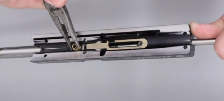
Transfer port removal
19:43 Use a set of tweezers to remove the plunger.
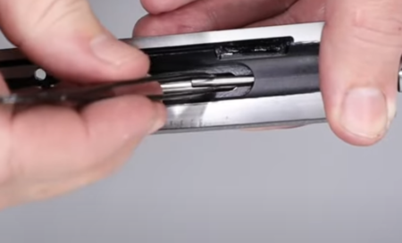
The indexing arm plunger
19:52 Use a magnet to remove the spring. Place the magnets above the spring housing and move towards the open end.
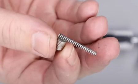
Behind the pin is a spring
20:09 Remove the four grub screws – two on the bottom of the top block and two shorter grub screws located on the underside forward of the slot using a 2mm allen key. (20:22) This will allow the barrel to be pull free of the block.
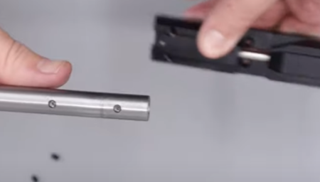
Barrel removal
REMOVING THE PELLET PROBE
20:56 Remove the spring ball de-tent at the top of the block just forward of the cocking bolt. Use a 2mm allen key to first remove the grub screw. Use a magnet to remove the small spring and ball bearing underneath.
21:19 The cocking dog is removed by using a 3/32 allen key to remove the allen bolt in the cavity on the underside of the top block. These can be quite tight and also held in place with a small amount of Loctite.
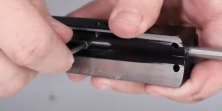
Removing the cocking dog (bolt pin)
21:36 Pull the cocking bolt free from the top block.
REMOVING THE TRIGGER HOUSING AND MAIN BOARD
22:10 Disconnect the coil wires by disconnecting the lager of the two plastic connectors on the electronic board. Push down on the tab (22:21) then use a set of tweezers or small set of long nose pliers to pull the block free. Do not pull on the wires.
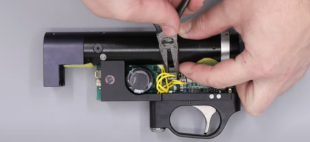
Do not pull on the wires
22:38 Remove the trigger housing from the block by loosening the bolt locate in a hole forward of the trigger using a 3/16 allen key. This will allow you to lift off the trigger housing and circuit board.
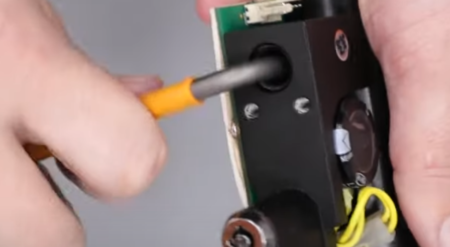
Removing the trigger unit from the action
DISASSEMBLING THE HAMMER HOUSING AND REMOVING THE COIL
23:06 Use a 1/16 allen key to remove the two grub screws at the rear of the block to remove the safety housing. (23:18) Keep a grip on the safety as it is sprung.
23:27 The hammer and hammer return spring can be removed from the back of the block.
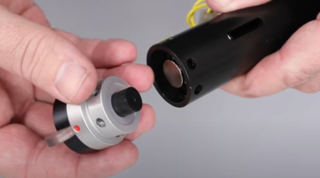
Safety and hammer removal
23:31 The retention ‘o; ring can also be removed from the back of the block.
23:39 Remove the aluminium spacer from the rear of the block.
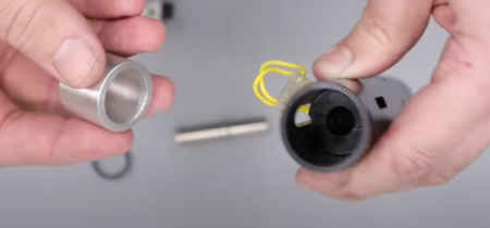
Most rifles have this spacer, on later rifles the spacer is replaced with a longer solenoid
23:51 To remove the coil, lay the wires down into a small cut out in the coil housing. Then push the wires through the slot in the block and pull the coil and coil housing free using a set of tweezers or small pair of long nose pliers to ease the coil through the back of the block.
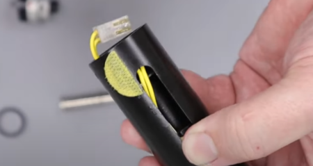
Solenoid removal
25:18 Use a long flat bladed screwdriver through the block to undo the brass nut inside and remove the component from the end of the block. Take care to not lose a small ‘o’ ring behind the brass nut. You may need to pick the ‘o’ ring free using a small flat blade screwdriver or similar.
DISASSEMBLING THE SAFETY
26:06 Remove the grub screw at the back using a 1.5mm allen key. Remove the small spring and ball bearing behind using a magnet.
26:29 Remove the rubber bung from the other side of the safety catch housing by hand to expose a bolt that can be removed using a 5mm allen key. This will allow the two halves of the safety housing apart.
26:55 The plastic safety switch can be removed by pulling it free by hand. Note though that it may be glued in at the factory.
REMOVING THE MAIN CIRCUIT BOARD
27:15 To remove the circuit board from the trigger housing, tip out the bolt that holds the trigger housing onto the block that was loosened earlier.
27:25 Disconnect the remaining three connector plugs, pushing in the tabs and then using a small set of long-nose pliers or tweezers to pull the blocks. Do not pull the wires.
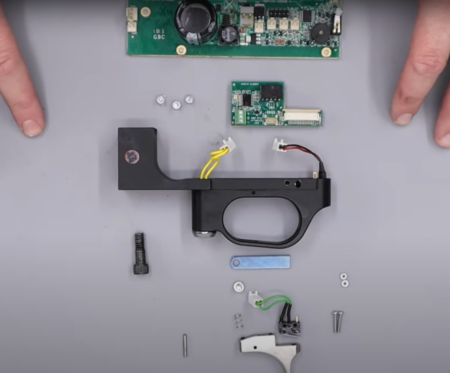
The Air Wolfs CDT board and trigger components
28:25 To remove the circuit board from the trigger housing you will need to undo three small screws using a small blade bladed screwdriver. Peel back the white tape to expose two of the screw heads. (28:47) You will need to locate the third screw locate under the tape towards the top corner forward of the trigger and then cut a small flap to access the screw head. Once removed, you will be able to lift off the circuit board.
DISASSEMBLING THE TRIGGER
29:28 The trigger blade is removed from the trigger assembly by undoing the screw immediately above the front of the trigger guard using a flat blade screwdriver. (29:34) Note there a small spring under the plate.
29:40 Hook out the spring.
29:51 Use a thin allen key to push out the pin in the side of the trigger housing immediately above the front of the trigger blade. This will allow the trigger blade to be removed through the top of the housing.
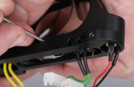
Trigger blade removal
30:15 The trigger switch is removed by loosening the two screws using a small flat bladed screwdriver. Take care to not lose the two nuts behind. (30:31) Use a magnet to pull the screws out of the two holes. (30:49) This will allow the trigger switch to be removed.

Removing the trigger switch
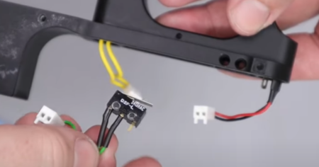
Trigger switch removed
