THE AIR WOLF
Assembly Guide
ON THIS PAGE
- Tools you will need
- Rebuilding the trigger
- Installing the main circuit board
- Rebuilding the safety
- Rebuilding the hammer and coil assembly
- Installing the trigger
- Installing the pellet probe
- Installing the barrel
- Installing the LCD screen
- Joining the top and bottom halves of the block
- Installing the daughter board
- Rebuilding the bottle housing
- Installing the valve and bottle housing
- Testing the rifle functions
- Rebuilding/installing the shroud
- Installing the bottle
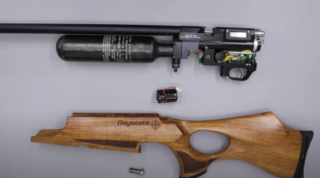
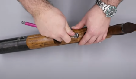
- Installing the stock
INTRODUCTION
Daystate air rifles are engineered to the highest standards, but like anything else, they require repairs and servicing work to be carried out both in and out of warranty.
The aim of this guide and the accompanying video is to help you undertake work on the Daystate Air Wolf to address common faults.
Compressed air is dangerous. You should only use this guide if you are a qualified and experienced gunsmith used to working with compressed air. Before you carry out any work on the Daystate Wolverine, or any PCP air rifle for that matter, you must ensure it is not cocked, not loaded and empty of air.
TOOLS YOU WILL NEED (00:33)
- Allen keys: 1.5mm, 2mm, 2.5mm, 3mm, 4mm, 5mm. 1/16, 3/32, 3/32, 5/16 inch
- Long nose pliers
- 16 mm spanner
- Adjustable spanner
- Triangular anti-tamper tool
- Tweezers
- Flat blade screwdriver: 3mm, 6mm, 12mm
- Magnets
REBUILDING THE TRIGGER
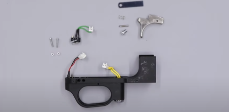
Trigger assembly
01:44 Align the hinge on the trigger switch with the front of the trigger block.
01:49 Align the two holes in the switch with the two holes in the side of the trigger block and drop the two screws through to hold the switch in position (01:58).
02:07 Use a flat bladed screwdriver to push the screws through and then attach the small nuts from the other side.
02:19 Align the top of the trigger switch with the trigger block and tighten the screws using a flat blade screwdriver.
02:39 Put the trigger blade through the top of the trigger block, aligning the small hole in the trigger blade with the hole in the trigger block.
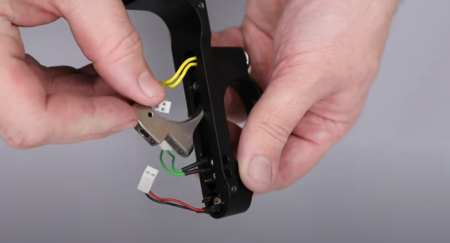
Inserting the trigger blade
02:52 Secure the trigger blade by inserting the small pin.
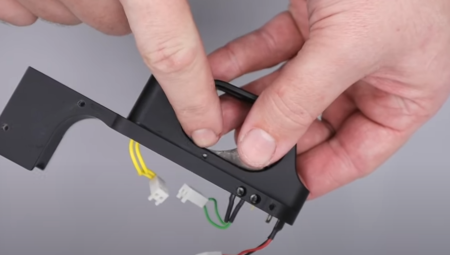
Trigger dowel inserts here
03:07 Take the trigger weight spring and drop it into the hole in the middle of the trigger blade from the top of the trigger block.
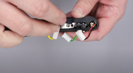
Trigger spring has a brass spacer
03:10 Cover the top of the trigger blade by attaching the trigger plate. The hole faces towards the front of the trigger and the plate is secured using with a screw. Note the screw does not need to be done up tight – just enough to feel a small amount of resistance on the blade is sufficient and hear the trigger switch click when the trigger is pulled.
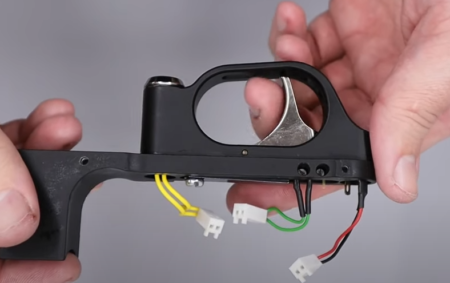
Test the trigger switch operates before proceeding and adjust as necessary
INSTALLING THE MAIN CIRCUIT BOARD
04:14 Position the circuit board so the capacitor is aligned with the curved end to the trigger block and the holes in the board align with the holes in the trigger block. Secure with the three screws using a flat blade screwdriver (04:37).
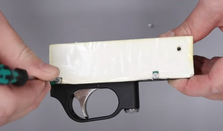
3 screws attach the CDT motherboard
05:17 The lock is the forward most connector. Use a pair of tweezers to locate the block into the connection closest to the coil and push home.
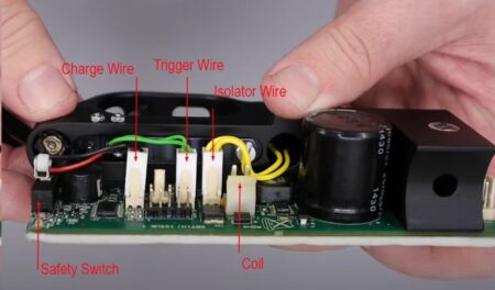
Plug socket attachments
05:26 The trigger connection is the middle wide. Insert into the connector block next to the lock connector.
05:36 The charging wire is connected to the end connector block.
REBUILDING THE SAFETY
06:28 Take the large safety component and add a small amount of moly grease to the back.
06:43 Take the safety back and place to the corresponding component taking care to align the pin with the hole.
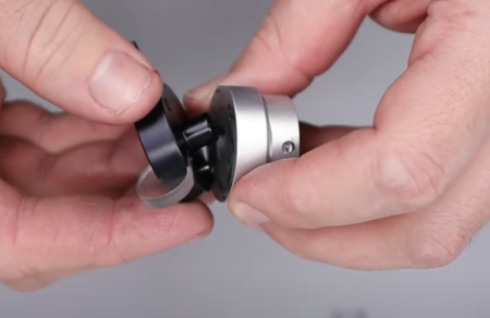
Assembly of the safety catch
06:55 Drop the securing screw the hole having first applied a small amount of Blue Loctite to the thread. Tighten with a 5mm allen key.
07:20 Apply a small amount of moly grease to the small hole on the back of the safety then drop in the ball bearing followed by the spring. (07:38) Secure with the grub screw, tightening with a 1.5mm allen key.
08:02 Place the rubber bung over the hole in the front of the safety and push home.
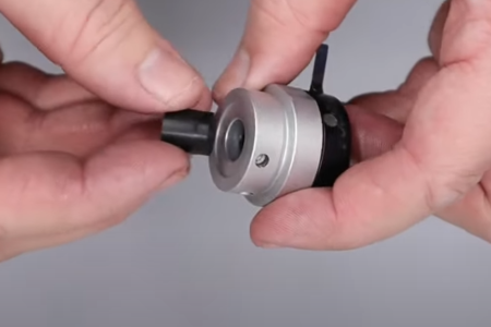
Anti-bounce rubber bung needs to be fully pushed home
REBUILDING THE HAMMER AND COIL ASSEMBLY
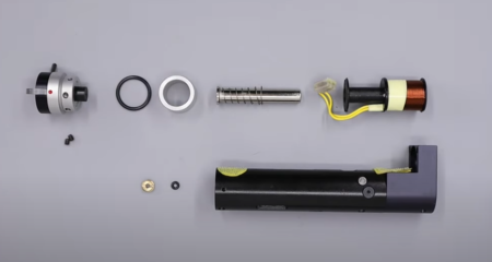
08:23 Apply a small amount of silicon grease to the valve seal ‘o’ ring. (08:32) Drop the ‘o’ ring into the hammer assembly and locate into the seat at the bottom using a long flat bladed screwdriver or similar.
08:56 Take the brass nut and drop that into the hammer housing on top of the ‘o’ ring, using a long flat bladed screwdriver to position correctly ensuing the side with a screwdriver slot is uppermost.
09:15 Use a long flat bladed screwdriver to tighten the nut in place.
09:40 Locate the small cut out in the top of the coil and lay the wires flat across it.
09:47 Insert the coil into the hammer housing and push home ensuring the wires are aligned to the be exposed through the slot (10:02).
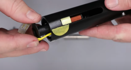
Take care not damage the coil wire
10:06 Tease the wires and connector block through the slot using a pair of tweezers.
10:24 Drop the hammer into the back of the housing spring end first then drop the aluminium spacer on top. (10:32) Place the large ‘o’ ring on top of the spacer.
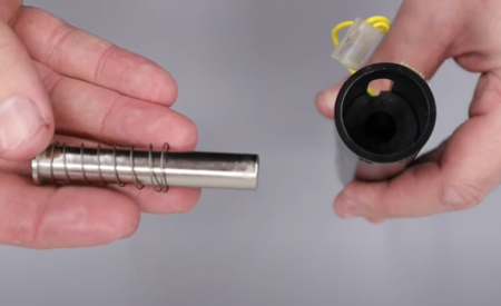
Hammer and spring assembly, note the later flared spring
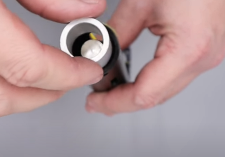
Inserting the spacer
10:45 Secure using the safety block, aligning the two dimples in the safety housing with the two screw holes in the end of the hammer housing (10:44).
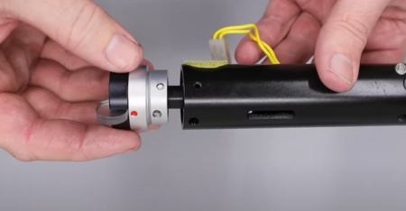
Replacing the safety catch
10:55 Insert and tighten the two screws using a 1/16mm allen key.
INSTALLING THE TRIGGER
11:30 Lay the hammer housing on its back with the coil wire uppermost. Place the trigger housing on top, aligning the large hole at the front of the trigger housing with the hole in the bottom of the hammer housing (11:37).
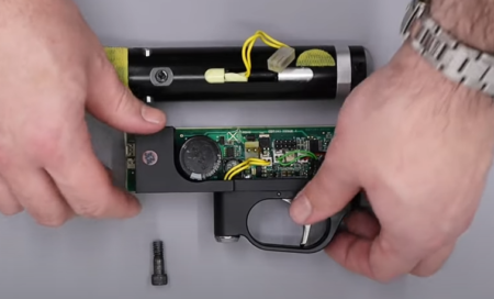
Attach the trigger group assembly
11:43 Drop the bolt in and tighten with a 3/16 allen key. Ensure none of the wires are pinched before fully tightening.
12:00 Plug the coil wires into the connector at the front top of the circuit board. Ensure the tab on the connector is orientated towards the top of the rifle. (12:19) Ensure the coil wires lie on the left of the circuit board towards the capacitor itself.
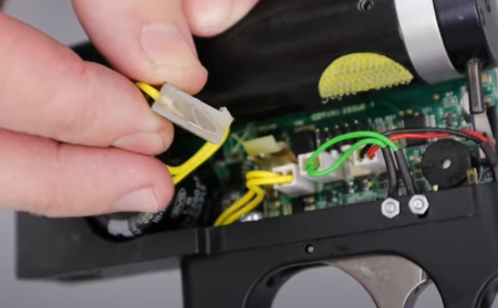
Attaching the coil assembly
INSTALLING THE PELLET PROBE
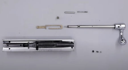
Breech block assembly
12:41 Add a small amount of moly grease or lithium grease to the pellet probe.
12:59 Insert the pellet probe through the hole on the bottom of the top block from the rear, aligning the counter bore in the pellet probe uppermost.
13:10 Add a small amount of Blue Loctite to the thread on the cocking dog and insert into the counter bore hole on the top of the pellet probe using a 3/32 allen key.
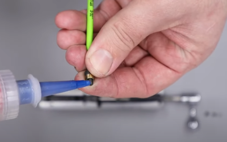
Cocking dog should be affixed with a small drop of Loctite
13:30 Push the pellet probe into the top block and add a small amount of moly grease to the small hole at the back end of the block just above where the pellet probe is first exposed.
13:39 Take the spring and push into the hole. Apply a small amount of moly grease to the top of the spring (13:49) before adding the pin (13:53).
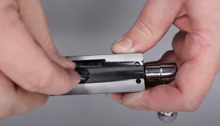
Insert this spring
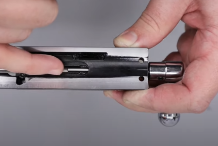
…then the pushrod
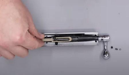
…and then the indexing arm
14:06 Apply a small amount of moly grease to the sides of the slot at the top of the block. Locate the indexing system on top with the cut out so the flat side is uppermost.
14:38 Turn the block over so it is the right way up. Apply a small amount of moly grease to the middle hole at the rear of the block by the cocking bolt and drop in the 1/8th ball bearing followed (14:51) by the spring (14:55). Secure with the grub screw (15:59) using a 2mm allen key.
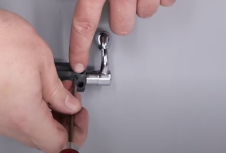
Bolt detent spring should not be overtightened
INSTALLING THE BARREL
15:35 The counter bore in the back of the barrel needs to be aligned with the bottom of the block.
15:38 Push the barrel into the block aligning the two dimples in the barrel with the two holes in the bottom of the block.
15:52 Secure the barrel using the four grub screws inserted into the top and bottom of the block. The two shorter grub screws go into the bottom of the block and the two longer grub screws go into the top. Use a 2mm allen key to tighten.
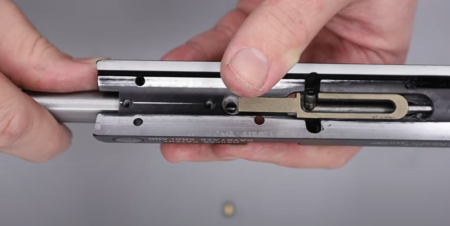
Replacing the barrel which is secured by 4 screws
16:25 From the underside of the block, pull the cocking bolt back taking care not to unseat the indexing system. Insert the transfer port (16:35) after applying a small amount of silicon grease.
INSTALLING THE LCD SCREEN
17:05 Add a small amount dialectric grease to the back of the screen.
17:22 Feed the ribbon cable through the slot in the side of the top block.
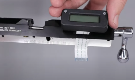
Feeding the display screen through the slot in the breech block
17:37 Push the screws through the screen so they locate in the holes in the side of the block. Tighten using a flat bladed screwdriver to tighten.
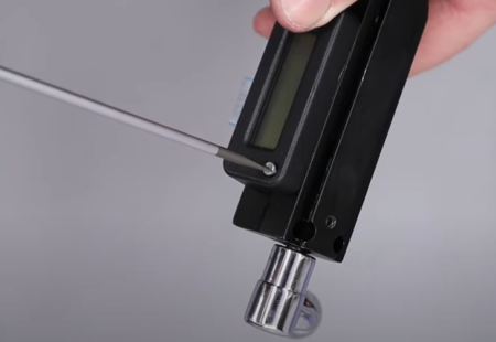
Do not overtighten these screws
JOINING THE TOP AND BOTTOM HALVES OF THE BLOCK
18:21 Feed the end of the ribbon cable through the slot in the side of the lower block so it emerges the other side.
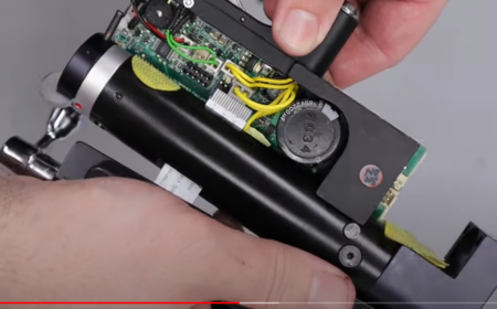
Feeding the display tape through the rear housing
19:07 Use the six securing screws to join the top and bottom block together. (19:17) The counter sunk bolts are inserted into the two holes next to the breech and tightened using a flat bladed screwdriver.
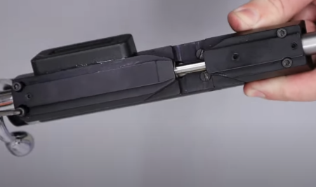
Replace all 6 screws
19:30 The four cap headed bolts are installed – two in the front of the top block and two in the rear – using a 2.5mm allen key.
INSTALLING THE DAUGHTER BOARD
19:54 Insert the ribbon cable into the connector on the daughter board. (19:59) Ensure the tab on the connector is pushed open and insert the ribbon and once in position, lock the securing tabs on the connector block.
21:28 The daughter board is installed onto the main board by aligning black box on the daughter board with the ten-pin connector on the main board (20:26).
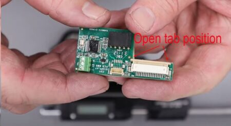
Display daughter board with the display ribbon clip open
REBUILDING THE BOTTLE HOUSING
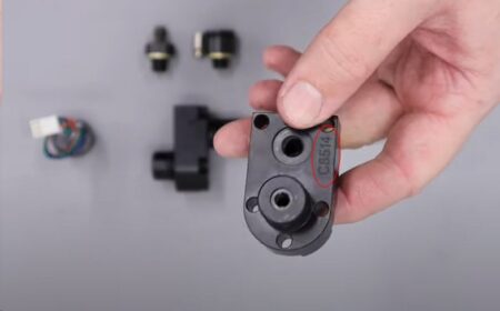
Original B housing should be replaced these numbers indicate an earlier housing
22:27 Add a small amount of silicon grease to the ‘o’ ring on the rear of the bottle connector.
22:41 The pressure sensor connector can be screwed into the hole below and tightened with an adjustable spanner or 22mm spanner.
23:00 Add a small amount of silicon grease to the one-way valve.
23:06 Drop the one-way valve into the foster fit housing with the screwdriver slot and ‘o’ ring uppermost. (23:18) Screw on the spacer piece and install into the bottom of the bottle housing (23:23) tightening with a 16mm spanner.
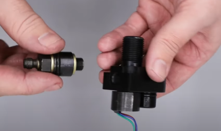
Filler assembly being replaced
INSTALLING THE VALVE AND BOTTLE HOUSING
24:05 Take the valve seat and apply a light coat of silicon grease to the outside ‘o’ ring.
24:14 Locate the counter bore side of the valve seat and push the valve pin through.
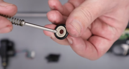
Valve seal inserts this way up
24:32 Install the valve pin and valve seat into the block through the upper hole at the front of the block.
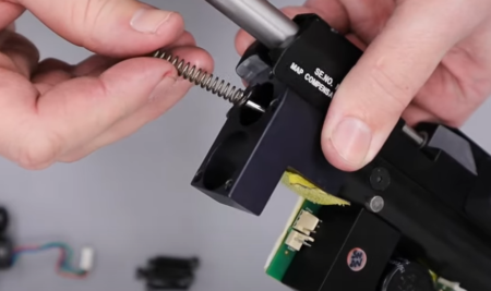
Valve and its seal being replaced
24:54 Feed the pressure sensor wires and connector through the bottom hole on the front of the block.
25:10 Push the bottle housing against the front of the main block into the two holes. (25.23) Secure with the five bolts through the front of the bottle housing, tightening with a 4mm allen key.
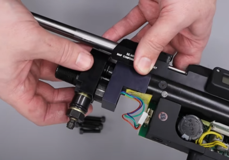
Replacing the bottle housing
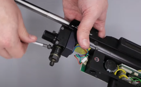
5 screws secure the bottle housing
TESTING THE RIFLE FUNCTIONS
26:14 Connect the pressure sensor to the main board by attaching the wires to the connector to the three-pin connection at the top of the main circuit board at the front of the main block.
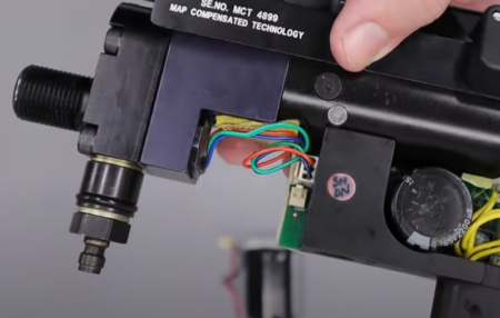
Sensor attachment
26:36 Locate the connector on the battery and orientate the two ears on the block with the top of the rifle and snap onto the battery terminal located just below the pressure sensor connector.
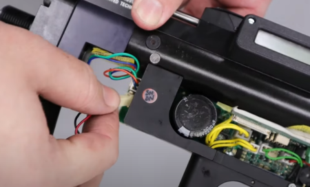
Battery attachment
26:59 The battery locates in the cavity immediately in front of the connector block and behind the foster fit and is held in place with velcro.
You will now be able to test the electronic components and functions to ensure proper operation.
NOTE: It is advised that you disconnect the battery again prior to continuing the re-assembly.
REBUILDING / INSTALLING THE SHROUD
28:35 Take the barrel spacer and baffle tube and push into the muzzle end of the shroud.
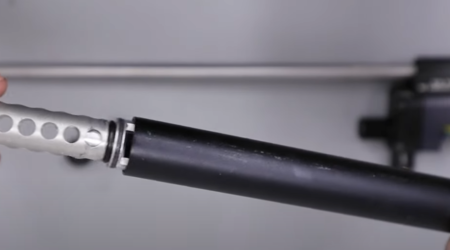
Baffle attachment
28:46 Screw in the end cap and tighten with a flat blade screwdriver.
29:01 Locate the cut out in the rear of the shroud and align with the top of the bottle housing. Ensure the two grub screws stand proud to ensure they do not catch on the barrel.
29:13 Slide the shroud over the end of the barrel and tighten the two grub screws using a 2 mm allen key. Ensure a slight gap between the end of the shroud and the block.
INSTALLING THE BOTTLE
31:16 Add a small amount of silicon grease to the large ‘o’ ring and locate into the neck of the air bottle then screw the bottle onto the front of the bottle housing by hand.

Bottle ‘o’ ring should be checked and in good condition

