THE PULSAR
Disassembly Guide
ON THIS PAGE
- Tools you will need
- Removing the stock and degassing the rifle
- Removing the barrel and disassembling the shroud
- Removing the cylinder assembly
- Removing the trigger assembly
- Removing the main circuit and board assembly
- Removing the pressure sensor and valve assembly
- Removing the hammer assembly
- Removing the cocking arm and pellet probe
- Removing the magazine indexing system and valve
- Disassembling the main circuit board
- Disassembling the trigger assembly
INTRODUCTION
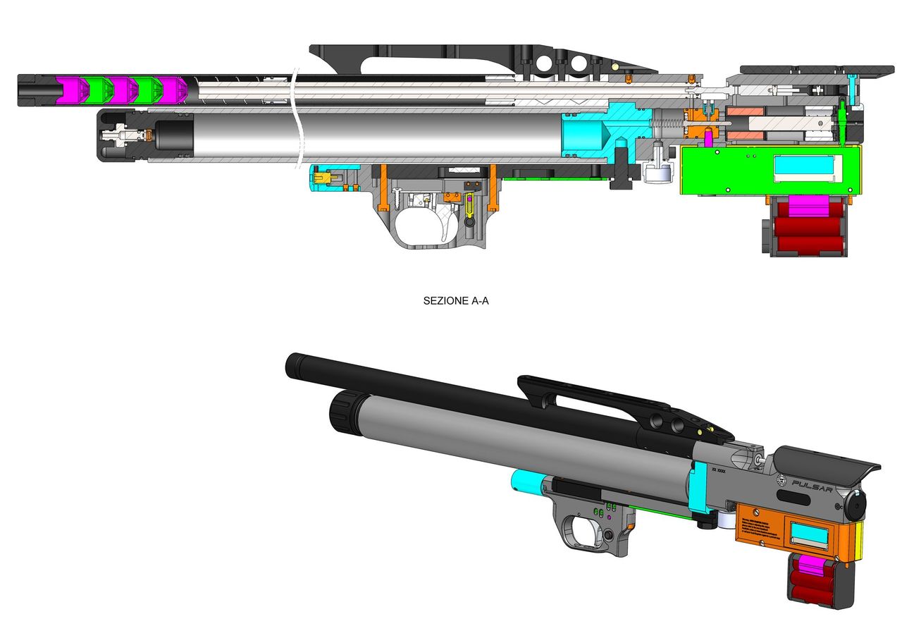
The Daystate Pulsar and Red Wolf share common components to the earlier Pulsar. Utilising a new Electronic board design called a gun control unit (GCU), the Pulsar incorporating some novel ideas such as a built-in laser and a bolt-open safety, which was carried across to the Red Wolf model when it was introduced 2 years later.
Daystate air rifles are engineered to the highest standards, but like anything else, they require repairs and servicing work to be carried out both in and out of warranty.
The aim of this guide and the accompanying video is to help you undertake work on the Daystate Pulsar to address common faults.
Compressed air is dangerous. You should only use this guide if you are a qualified and experienced gunsmith used to working with compressed air. Before you carry out any work on the Daystate Pulsar, or any PCP air rifle for that matter, you must ensure it is not cocked, not loaded and empty of air.
TOOLS YOU WILL NEED
- Allen keys: 1.5mm, 2mm, 2.5mm, 3mm, 4mm and 5mm
- Spanners: 16mm, 17mm, adjustable
- 3 pin tool
- Tweezers
- O ring pick
- 3mm wide flat bladed screwdriver
- Degassing tool
REMOVING THE STOCK AND DEGASSING THE RIFLE
1:05 Cock the rifle and remove the magazine or single shot loader. Dry fire the rifle into a safe backstop.
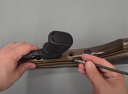
01.25 Removing the stock
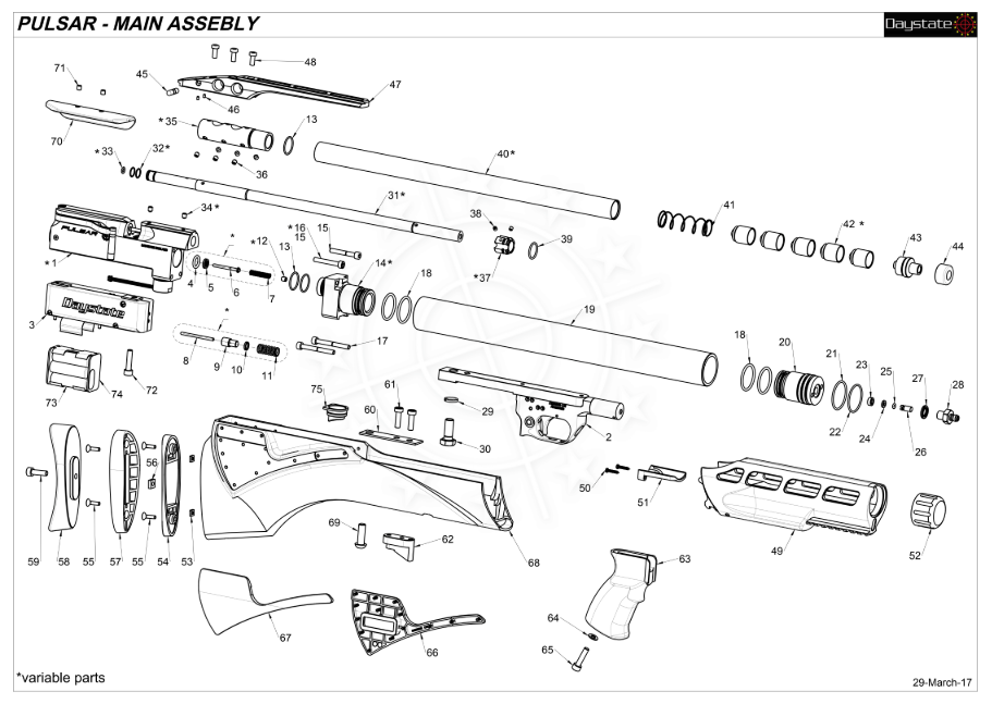
01:25 Remove the stock by undoing the bolt on the underside of the rifle using a 5mm allen key. This will allow the stock to be lifted off the action. Ensure the safety catch is in the safe position (01:46).
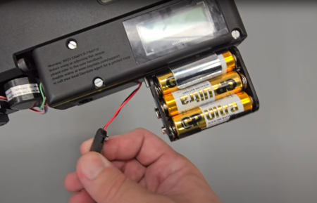
01.55 Disconnect the battery pack
01:55 Disconnect the battery by pulling the connection to the battery pack off, then pull the battery pack off (02:44).
02:18 If you intend working on the electronic components to the rifle, it is recommended that you disconnect the battery and leave the rifle overnight in order for any residual charge in the capacitors to dissipate.
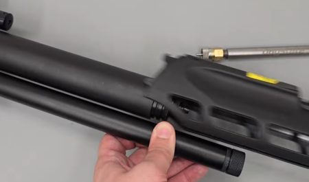
02.39 Removing the forend
02:39 Remove the filler valve end cap. The slide the plastic air cylinder cover off (02:46).
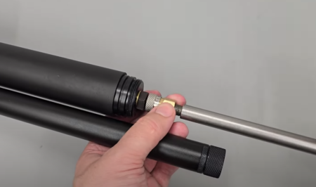
02.53 Using a degassing tool to drain the air
02:53 Use a Daystate de-gassing tool and remove the fitting from the end and place over the filler valve on the rifle. Screw the degassing tool into the back. After a few turns you will feel the tool engage with the one-way plunger in the fill valve. A few more turns will result in the air escaping.
03:23 Remove the tool once the air has stopped hissing.
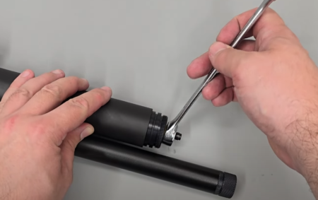
03.40 Alternative method is to carefully loosen the filler valve assembly
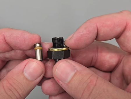
03.40 Filler component
03:40 To ensure the rifle is fully degassed, take a 16mm spanner and loosen the foster fitting.
05:03 Remove the spacer from the end of the air cylinder.
REMOVING THE BARREL AND DIASSSEMBLING THE SHROUD
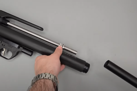
05.15 Shroud removal
05:15 Unscrew the shroud by hand. Be aware that at the front of the shroud there is a series of baffles as well as a spring.
05:55 The scope rail can be removed from the top of the rifle by loosening the three securing screws using a 3mm allen key.
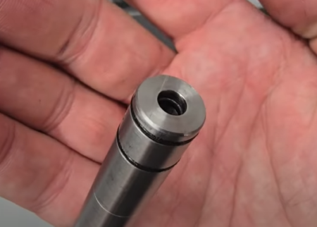
06.22 Detail of the 3 ‘o’ rings
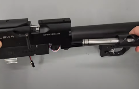
06.22 Remove the barrel which can be removed with the shroud in place
06:22 To remove the barrel, loosen the two grub screws using a 2.5mm allen key. With the screws loosened, the barrel will pull away from the block.
06:37 The shroud support can be removed from the barrel by loosening the six grub screws using a 2.5mm allen key. With the six screws loose, the shroud support will slide off the barrel.
07:13 The front shroud carrier is removed by loosening the two grub screws using a 2mm allen key.
08:25 The cheek piece is removed by loosening the two grub screws using a 2.5mm allen key.
REMOVING THE CYLINDER ASSEMBLY
08:40 The cylinder unscrews from the main block by hand.

08.58 A tool is needed to unscrew the cylinder cap
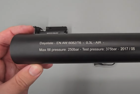
08.58 Air tube are lifted at 10 years from first use
08:58 To remove the cap from the other (muzzle) end of the cylinder, use either a set of pin nose pliers or snap ring pliers, or better still, a pin tool.
REMOVING THE TRIGGER ASSEMBLY
10:08 Access the circuit board by removing the three screws using a flat bladed screwdriver and then lifting off the cover.
10:43 Remove the connection for the trigger which is located at the front of the circuit board at the bottom. Take care to pull on the plastic block and not the wires.
11:19 Remove the trigger plate from the action by loosening the nut with a 17mm spanner.
REMOVING THE MAIN CIRCUIT BOARD ASSEMBLY
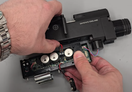
12.10 Disconnecting the coil wires
12:10 Disconnect the coil wires by loosening the two screws with a flat bladed or cross headed screwdriver.
12:23 The trigger plate is removed by loosening the screw at the bottom using a 5mm allen key.
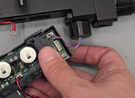
12.45 Disconnect the pressure sensor
12:45 The pressure sensor is still connected. To remove it, disconnect the plastic connector block on the circuit board, again taking care not to pull on the wires themselves.
REMOVING THE PRESSURE SENSOR AND VALVE ASSEMBLY
13:23 The pressure sensor can be removed by unscrewing it from the underside of the main block using an adjustable spanner.
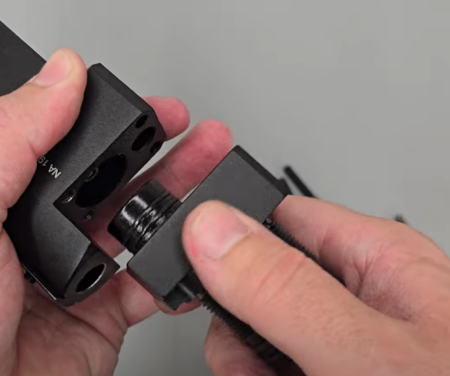
13.45 Cylinder housing removal
13:45 To remove the cylinder housing remove the four securing screws – two on the top and two underneath, using a 4mm allen key. Note that the two longer screws go in the bottom of the block and the two shorter screws go in the top of the cylinder housing (14:43).
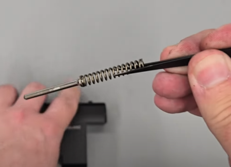
14.49 Valve pin
14:49 use a pair of tweezers to remove the valve pin and valve return spring from the large hole at the bottom of the main block.
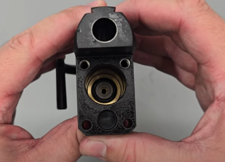
14.59 Valve seat in position
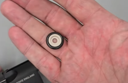
14.59 Valve seat removed
14:59 The valve seat can be removed by simply tapping the block against your hand or any hard surface. If it is a little stuck, then use a plastic pick to free it.
REMOVING THE HAMMER ASSEMBLY
NOTE: Anti-tamper bolts are fitted to sub 12 ft/lbs rifles.
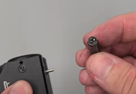
16.06 Anti-tamper bolt removal tool
16:06 Two anti-tamper bolts at the rear of the action need to be removed using a Daystate anti-tamper tool.
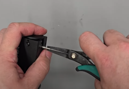
16.56 Safety end plug can be pulled out using a pair of pliers to pull the pin down
16:56 The safety end plug can be pull out using a pair of pliers to pull the pin down and then sliding the back section out of the rear of the block.
17:15 The hammer can then be tapped out of the rear of the block along with a wave ring and the hammer return spring.
17:31 A plastic spacer plug can then be pulled from the back of the block by hand.
17:40 The coil is removed by first bending the connecting wires back and into the action out of the way. The coil can then slide out of the rear of the action.
REMOVING THE COCKING ARM AND PELLET PROBE
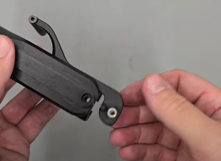
18.12 Removing the cocking arm and pellet probe
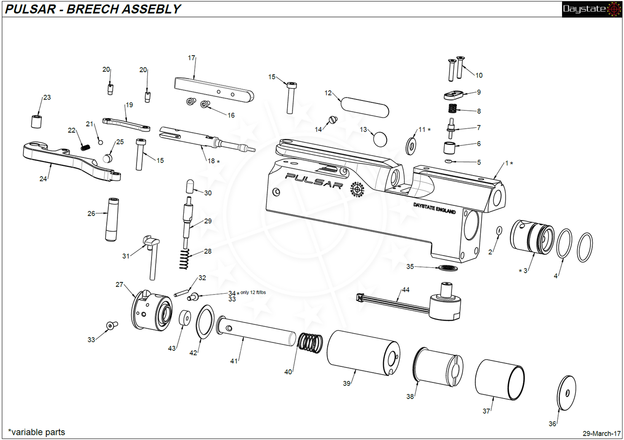
18:12 To remove the cocking arm and pellet probe, use a 2.5mm allen key to remove the screw at the top on the back of the action. This will allow the pellet probe and cocking arm to slide out the back of the action. Take care to not lose the cocking arm bush (18:30).
18:42 To separate the cocking arm and the pellet probe, use a small flat bladed screwdriver to loosen the small grub screw on the pellet probe.
19:06 The linkage can be removed from the cocking arm by undoing the small grub screw using a flat bladed screwdriver.
19:41 A small spring and ball bearing can be removed from the behind the linkage by using a set of tweezers.
REMOVING THE MAGAZINE INDEXING SYSTEM AND VALVE
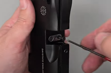
20.05 Undoing two small allen screws at the bottom of the breech using a 2mm allen key
20:05 The magazine indexing system is removed by first undoing two small allen screws at the bottom of the breech using a 2mm allen key. 20:22 Remove the small spring belong the plate and the magazine indexing plunger, cup and ‘o’ ring using a set of tweezers.
21:20 To remove the core valve from inside the action first tip out the spacer ring from the rear of the action.

21.29 Removing the core valve
21:29 The core valve can then be removed by pushing on one of the two holes in the back of the valve using a long rod through the back of the block. The valve will then emerge from the front of the block.
DISASSEMBLING THE MAIN CIRCUIT BOARD
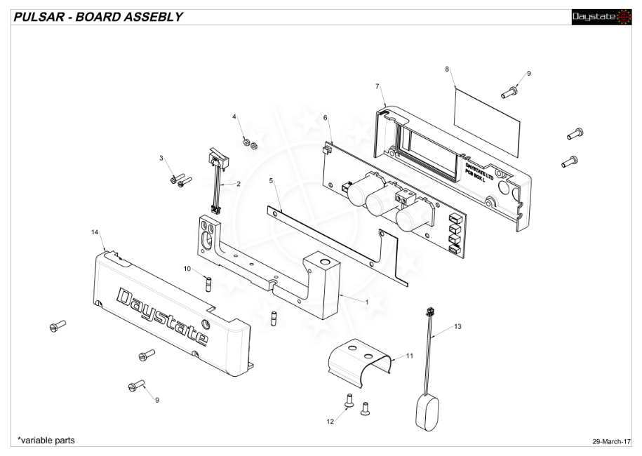
22:51 The battery housing is removed by undoing the two allen screws using a 2mm allen key.
23:07 The cocking sensor is located at the top of the rear of the circuit board and is removed by pulling the plastic connector block free, taking care to not pull on the wires.
23:28 Removed the three securing screws on the other side of the circuit board using a flat headed screwdriver.
23:44 Remove the screen cover. Then remove the main circuit board.
24:03 The insulating cover can be removed from between the trigger housing and the circuit board.
24:15 The battery connection wire can be removed by pulling the connector free, taking care to not pull the wires.
DISASSEMBLING THE TRIGGER ASSEMBLY
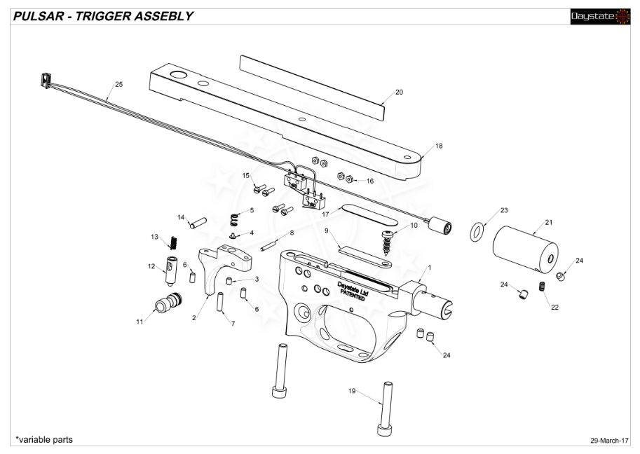
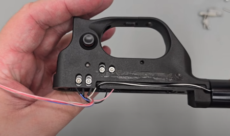
24:41 Pick the wires out from the housing, removing the tape as you go.
24:58 Separate the top piece of the trigger assembly by loosening the two screws using a 4mm allen key.
25:22 Pick off the remaining tape to free the wires from the trigger assembly.
22:39 The two switches inside the unit are removed by first removing the four screws using a flat bladed screwdriver.
26:03 To remove the trigger blade, remove the cross headed screw at the top of the trigger unit using a crosshead screwdriver.
26:17 The spring plate can then be removed.
26:25 Use a small allen key to push out the pin in the trigger unit forward of the trigger blade. This will allow you to slide the trigger blade out of the top of the trigger unit.
27:48 Remove the four screws at the top rear of the trigger unit using a small flat bladed screwdriver. This will enable you to remove the two switches for the trigger (27:53). Take care to not lose the small nuts on the back.
28:23 With the screws pushed out, the switches can be lifted out of the top of the trigger unit.
28:31 The laser unit from the front of the trigger unit is removed by undoing the two grub screws using a 2mm allen key.
29:09 The safety catch is removed by pushing out the small pin above the safety catch. Take care to not lose the small spring from the top of the trigger unit as it may jump free.
29:22 The safety plunger can then be tipped out of the side of the trigger unit. The safety blade should fall out of the side.
